Recommended Articles
Mastering this diagram can solve 80% of hardware failures in inverters.
Application and programming of PLC communication using MODBUS protocol, a must-read for beginners!
How to use the FOR loop in SCL to make program design more efficient?
How to establish communication between two Siemens S7-200 SMART PLCs? Detailed implementation steps →
Bookmark this collection of essential knowledge for automation PLC!
After reading this article, communication between Siemens S7-1200 and S7 will no longer seem difficult~
How to read and write local real-time in S7-1200 PLC?
Polling case of controlling two inverters using BD board in Mitsubishi PLC.
Have you encountered the “pits” of timer usage in S7-1200?
Electrical automation control terminology, saved!
Why install encoders on motors? How do encoders work?
PROFINET communication between S7-200 SMART series PLCs.
In the implementation of PLC control systems, although the wiring phase accounts for a limited proportion of the overall workload, it is the prerequisite for program development—only by ensuring accurate wiring connections can subsequent programming work proceed smoothly. The key to achieving zero wiring errors lies in establishing a clear understanding of the principles and terminal definitions of the PLC’s internal input and output circuits.
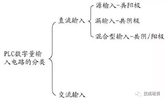
DC Input Circuit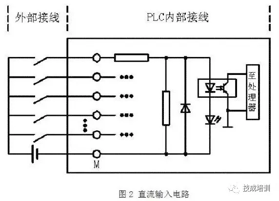
As shown in the above diagram, the following diagram illustrates a typical PLC DC input circuit (single-channel schematic):
When the external control switch is closed, the circuit forms a path, lighting the LED of the internal optocoupler, triggering the phototransistor to enter a saturated conduction state. This switch signal is transmitted to the processor via the internal circuit, allowing the CPU to determine it as “input valid”;
When the external switch is opened, the optocoupler’s LED turns off, and the phototransistor returns to the cutoff state, which the CPU immediately recognizes as “no input signal”.
This optoelectronic isolation design ensures the safe isolation of external high voltage from the internal low voltage system while reliably detecting the switch state through optical signal transmission.
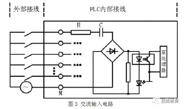
As shown in the above diagram, the difference between the AC input circuit and the DC input circuit is mainly the addition of arectification stage.
The AC input circuit typically connects to AC120V or 230V voltage, and its working path is: the AC current first passes through a resistor R for current limiting, then through a capacitor C for isolation, and is converted to DC through a bridge rectifier circuit. The subsequent optocoupler detection and signal processing mechanism is identical to that of the DC input circuit.
Thus, it can be seen that the AC input circuit, due to the added current limiting, isolation, and rectification stages, results in a longer input signal delay time compared to the DC input circuit, which is its inherent limitation; however, thanks to the high voltage design at the input end, its signal transmission’s anti-interference capability and reliability are significantly superior to that of the DC input circuit.
Leakage Type Input Circuit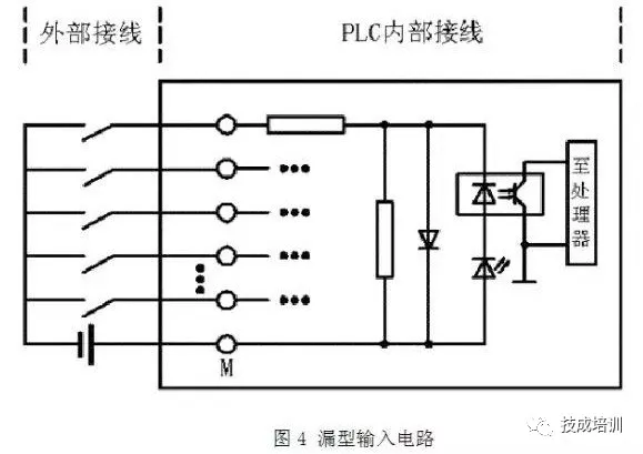
As shown in the above diagram, the current path is: flowing from the PLC common terminal (COM terminal or M terminal), through the internal circuit, and then out from the input terminal. Therefore, the positive terminal of the external DC power supply must be connected to the PLC common terminal.
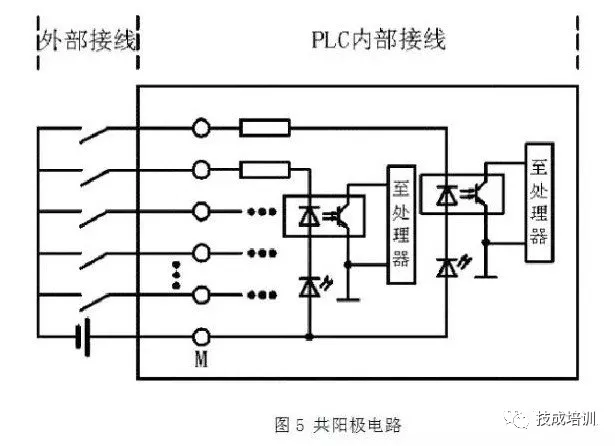
As shown in the above diagram, this illustrates a single-channel input circuit structure. To expand to multiple inputs, simply connect the anodes of all the LEDs in the input circuits together to form a common anode input circuit.
The leakage type input modules of Mitsubishi PLC include models AX40/41/42/50/60 of the A series and QX40/41/42 of the Q series.
As shown in Figure 3, this circuit represents a source type input structure, where the current flows from the PLC input terminal, through the internal circuit, and out from the common terminal. Therefore, the common terminal must be connected to the negative terminal of the external power supply.
If the cathodes of all the LEDs in the input circuits are connected together, a common cathode input circuit can be formed. As shown in the following diagram:
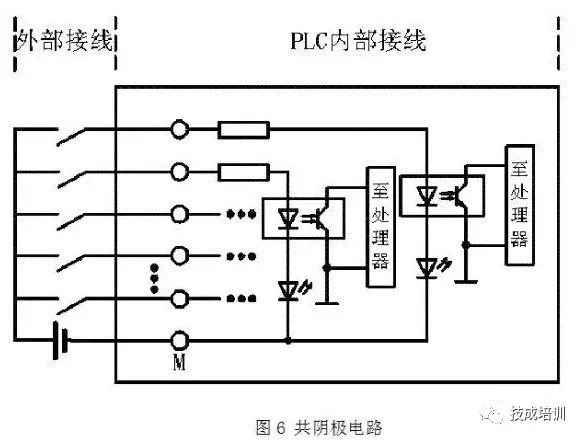
The input modules of Mitsubishi PLC that use this type of circuit include models AX80/81/82 of the A series and QX80/81 of the Q series.
Hybrid Input Circuit
This type of PLC supports flexible wiring at the common port (can connect to either the positive or negative terminal of the external power supply), combining the characteristics of both source type and leakage type input circuits, hence it can be referred to as a hybrid input circuit. As shown in the following diagram:
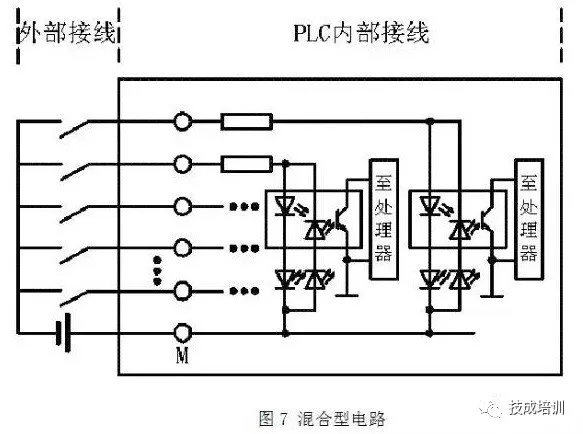
This circuit supports dual-mode wiring: when used as a source input, the common terminal connects to the negative terminal of the power supply; when used as a leakage input, the common terminal connects to the positive terminal of the power supply, allowing for flexible configuration based on site requirements, significantly enhancing wiring adaptability.
The hybrid input module models of Mitsubishi PLC include: AX50-S1, AX60-S1, AX70, AX71, AX81-S1 of the A series, and QX70, QX71, QX72 of the Q series.
It should be noted that Mitsubishi and Siemens have completely opposite definitions for “source input” and “leakage input” circuits; the classifications in this article are based on Mitsubishi’s standards.
Connection of External Switch Signals and PLC Input Circuits
The external input signals for PLCs include two types: one is dry contact signals such as buttons, and the other is NPN or PNP open-collector output signals provided by modern sensors.
However, when faced with different types of PLC input circuits, how to correctly match NPN or PNP type sensor input signals often becomes a point of confusion in actual wiring.
The following will focus on the connection methods of NPN and PNP type sensors with PLC input circuits. The diagrams illustrate the typical structures of NPN output circuits and PNP output circuits.
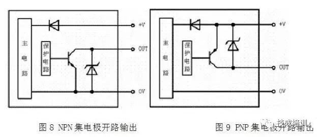
The OUT terminal of the NPN open-collector output circuit is connected to 0V through a switching transistor. When the sensor is activated, the switching transistor saturates and conducts, and the OUT terminal outputs a low level of 0V; the OUT terminal of the PNP open-collector output circuit is connected to +V through a switching transistor. When the sensor is activated, the switching transistor saturates and conducts, and the OUT terminal outputs a high level signal of +V.
Connection of NPN/PNP Output Circuits and PLC Input Modules
NPN Open-Collector Output
Based on the analysis above, the NPN open-collector output signal is 0V. When its OUT terminal is connected to the PLC input terminal, the current path flows out from the PLC input terminal and into the common terminal, which is the working mode of the PLC’s leakage type input circuit. Therefore, the NPN open-collector output is only compatible with leakage type or hybrid type input circuits of the PLC.
PNP Open-Collector Output
The PNP open-collector output signal is a high level of +V. When its OUT terminal is connected to the PLC input terminal, the current path flows into the PLC input terminal and out from the common terminal, which is the working mode of the PLC’s source type input circuit. Therefore, the PNP open-collector output is only compatible with source type or hybrid type input circuits of the PLC. The connection diagram is shown below:
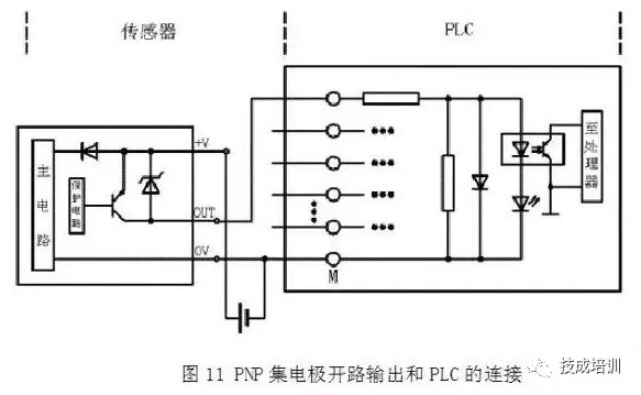
Due to the diversity of PLC input module circuit forms and the output signals of external sensors, it is essential to fully understand the input circuit types and sensor signal characteristics before wiring the PLC input module to ensure accurate connections, laying the foundation for subsequent programming and debugging work.
Recommended Articles
Mastering this diagram can solve 80% of hardware failures in inverters.
Application and programming of PLC communication using MODBUS protocol, a must-read for beginners!
How to use the FOR loop in SCL to make program design more efficient?
How to establish communication between two Siemens S7-200 SMART PLCs? Detailed implementation steps →
How to implement the positioning function of encoders using PLC control?
Have you encountered the “pits” of timer usage in S7-1200?
Polling case of controlling two inverters using BD board in Mitsubishi PLC.
How to read and write local real-time in S7-1200 PLC?
Bookmark this collection of essential knowledge for automation PLC!
After reading this article, communication between Siemens S7-1200 and S7 will no longer seem difficult~
Electrical automation control terminology, saved!
PROFINET communication between S7-200 SMART series PLCs.
Why install encoders on motors? How do encoders work?
Communication guide between Weintek touch screens and Mitsubishi PLC.