Click the blue text to follow immediately 01Introduction: PLC Arithmetic Instructions – The “Calculator” of Industrial ControlThe core of industrial control relies on precise data operations. Imagine that on a busy production line, the counting of each product, the adjustment of each motor’s speed, and even the precise control of material ratios all require the PLC (Programmable Logic Controller) to quickly “solve mathematical problems” in the background. These seemingly simple industrial operations actually hide the key role of PLC arithmetic instructions – they act like the “toolkit” of the control brain, determining the efficiency and accuracy of data processing.In the PLC’s “toolkit”,16-bit instructions and 32-bit instructions are the two most commonly used “problem-solving tools”. You can think of them as different specifications of “data containers”: 16-bit instructions are like a medium-sized box that can hold a certain range of values; while 32-bit instructions are a larger box that can accommodate much larger data. This metaphor of “data containers” will run through our subsequent content, helping you easily understand the differences and application scenarios of the two types of instructions.Core Cognitive Framework: The essence of PLC arithmetic instructions is as “data processing tools”, and the difference between 16-bit and 32-bit instructions is similar to “containers of different capacities”. The following chapters will guide you through specific operational scenarios, helping you master how to choose the appropriate “container” based on industrial needs, ensuring that PLC operations are both efficient and accurate.Whether it’s simple product counting or complex multi-axis motion control, choosing the correct instruction type is fundamental to ensuring the stable operation of industrial systems. Next, let’s open this “data container” together and see the “capacity secrets” of 16-bit and 32-bit instructions.
 0216-bit Arithmetic Instructions: Compact and Flexible “Data Small Box”
Analysis of the 16-bit Instruction Family (ADD/SUB/MUL/DIV)
In the world of PLC operations, the 16-bit instruction family is like a set of clearly defined “small box calculators” – each instruction specializes in a basic operation and obediently stores the result in the corresponding 16-bit register, just like we record results in a notebook after calculating with a calculator.Specifically,the ADD instruction is the “addition box”, responsible for adding two values and storing the result in the target register;the SUB instruction is the “subtraction box”, subtracting the subtrahend from the minuend and storing the difference;the MUL instruction is the “multiplication box”, calculating the product of two numbers and writing it to the register;the DIV instruction is the “division box”, performing division and storing the quotient (and remainder) in the specified register. Although these four “boxes” have different functions, they all follow the core logic of “operation-storage”, ensuring that data processing is fully traceable.These “small boxes” are very intuitive in industrial applications. For example, in a product conveyor counting system, when a sensor detects one product passing by, the PLC immediately calls the ADD instruction: it reads the value from the current count register, automatically adds 1, and then stores the updated quantity back into this 16-bit register. The whole process is like an accountant in a factory, adding a mark in the ledger for each product that comes in, clear and efficient.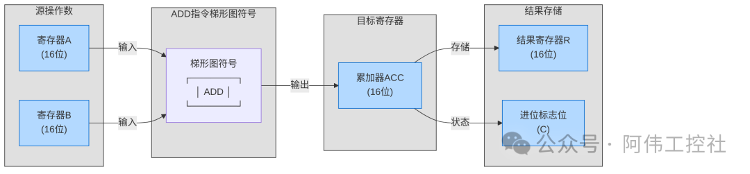 This image visually shows that the ADD instruction symbol in the ladder diagram connects to the sensor signal on the left (trigger condition), while the right side indicates the source register involved in the operation and the target register for storing the result, making the entire data flow clear. This “immediate calculation and storage” feature makes the 16-bit instruction family the main force in processing small to medium-sized data operations in industrial control.
Limitations of the 16-bit Instruction “Small Box”
In industrial data operations, the 16-bit instruction is like a fixed-capacity “small box” – it can efficiently handle values within a conventional range, but once it encounters a “large number” that exceeds its capacity, it will face the awkward problem of “not fitting”. This limitation can easily be encountered in actual production, such as when the daily output statistics of an automated conveyor belt exceed 32767; if the 16-bit ADD instruction is still used for accumulation, it will trigger an “overflow” phenomenon.Overflow Essence: The “small box” capacity of the 16-bit instruction is limited; when the operation result exceeds its maximum range, the PLC will experience data errors. This is like trying to continue stacking parts in a box that is already full; not only can new parts not fit, but the arrangement of existing parts may also be disrupted, leading to distorted statistical data.This type of operational anomaly caused by insufficient value range is a typical limitation of 16-bit instructions when processing large-volume production data. Understanding this will help us better recognize how the subsequent 32-bit instructions can solve such problems by “expanding the box”. We will elaborate on the specific data range comparison and selection methods between 16-bit and 32-bit instructions in the “Instruction Selection Guide” chapter. 0332-bit Arithmetic Instructions: A “Large Data Container” Created by Combining Two Boxes
Breakthrough of the 32-bit Instruction Family (DADD/DSUB, etc.)
When the PLC’s 16-bit registers are like small boxes filled with parts that can no longer accommodate larger numbers, engineers came up with a clever solution –to stick two small boxes together to form a large box. This is precisely the core design concept of the 32-bit instruction family, represented by instructions like DADD (Double Word Add) and DSUB (Double Word Subtract), which achieve a doubling of data storage capacity by combining two consecutive 16-bit registers.For example, with the DADD instruction, when performing double word addition, the result will be stored inD0 and D1, two consecutive 16-bit registers. Here, D0 typically stores the low 16 bits of data, while D1 stores the high 16 bits, together forming a complete 32-bit data space. This “combined storage” mechanism is like merging two adjacent drawers into a larger storage space, capable of accommodating larger values while maintaining the continuity of register addresses.Key Storage Feature: The operation results of 32-bit instructions must occupy consecutive registers; for example, the result of the DADD instruction will occupy both D0 (low 16 bits) and D1 (high 16 bits). When programming, care must be taken to avoid storing other data in consecutive addresses to prevent the operation results from being accidentally overwritten.In actual industrial scenarios, the advantages of 32-bit instructions are particularly evident. For instance, when monitoring high-precision motor speeds (such as over 10,000 RPM), the maximum value range of a 16-bit register (0~65535) may lead to overflow due to frequent calculations, while the maximum value supported by 32-bit instructions can reach 4294967295, sufficient to meet the continuous calculation needs in high-speed scenarios and ensure data accuracy. Through this layered storage structure, 32-bit instructions not only solve the data overflow problem but also provide reliable support for high-precision calculations in industrial control. Whether for complex motion control algorithms or large-scale data acquisition, instructions like DADD/DSUB have become the key bridge connecting PLCs with precision actuators.
Advantages of the 32-bit Instruction “Large Container”
In industrial automation control, the “capacity” of data operations directly determines whether the system can cope with the challenges of complex scenarios.The core value of 32-bit instructions lies in their ability to provide a “digital storage space” far exceeding that of 16-bit instructions, especially in scenarios requiring “large number operations”, where this “large container” feature demonstrates irreplaceable advantages.Industrial Scenario Pain Points: For example, in the feed control of a chemical reactor, the cumulative feed amount of a single reactor may reach millions of liters. If 16-bit instructions are used for calculations, their maximum representation range (-32768 to 32767) is far from sufficient, easily leading to calculation errors due to data overflow. In contrast, 32-bit instructions act like a “super-sized storage box”, easily accommodating such large number operations and ensuring the accuracy of long-term cumulative data. 04Instruction Selection Guide: Choosing the Right “Box” for the Right “Problem”
Data Range Comparison: Capacity Differences Between Small and Large Boxes
Understanding the data range differences between 16-bit and 32-bit instructions is like comparing storage boxes of different capacities – some are suitable for holding small items, while others can accommodate more. By comparing the sizes of the boxes (e.g., 16-bit instructions corresponding to “small boxes”, 32-bit instructions corresponding to “large boxes”), the capacity differences between the two can be visually observed.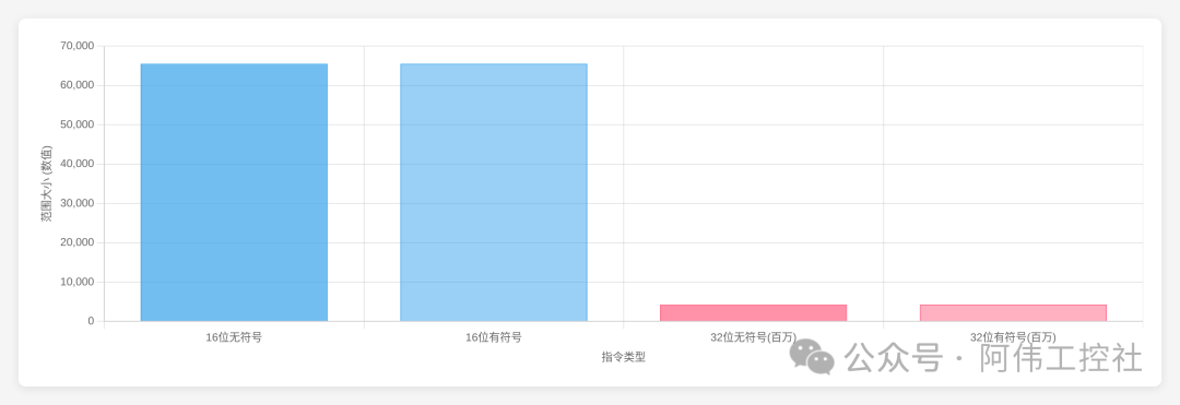 TableCopy
| Instruction Type | Signed Value Range | Register Occupation | Typical Application Scenarios |
|---|---|---|---|
| 16-bit | -32768 ~ 32767 | 1 16-bit register | Part counting, small device speed control |
| 32-bit | -2147483648 ~ 2147483647 | 2 consecutive 16-bit registers | Annual production statistics, large reactor control |
In industrial scenarios, the capacity of the “small box” is suitable for handling daily counting tasks, such as the real-time statistics of parts on the production line; while the “large box” is more suitable for cumulative totals, such as recording the total production data for an entire year. This difference is like using a small storage box for stationery and a large storage box for seasonal clothing; choosing according to need can avoid the problems of “not fitting” or “wasting space”.Practical Selection Guide: When counting the number of parts produced in a single shift, the “small box” of the 16-bit instruction is sufficient; however, when calculating the total production for the entire year, the “large box” of the 32-bit instruction is necessary to avoid data errors due to insufficient capacity.
Decision-Making Process: Three Steps to Choose the Right Instruction
In PLC arithmetic operations, selecting the correct instruction is key to ensuring accurate data processing. Many beginners often find themselves in a dilemma when faced with the differences between 16-bit and 32-bit instructions. In fact, by following a simple “three-step decision-making method”, you can quickly lock in the applicable instruction and avoid data overflow or calculation errors caused by incorrect instruction selection.Core Steps of the Three-Step Decision-Making Method
-
Determine the Data Range: Check if the operation data exceeds 32767 (for example, if the single shift output > 32767, use 32-bit). If it exceeds, choose the 32-bit instruction; otherwise, use the 16-bit instruction.
-
Determine the Operation Type: Clarify whether the requirement is for addition, subtraction, multiplication, or division.
-
Match the Corresponding Instruction: Based on the results of the first two steps, select the instruction, for example, use the DADD instruction for 32-bit addition and the SUB instruction for 16-bit subtraction.
By following these three steps, even beginners can systematically complete instruction selection. To better understand the process, refer to the decision-making flowchart below, which clearly displays the judgment logic of each step through diamond-shaped decision nodes and arrow flows, helping you accurately locate the required instruction like “finding a horse by its picture”. Whether processing simple counter values (usually 16-bit is sufficient) or high-precision measurement data from industrial instruments (which may require 32-bit), this method ensures that you take fewer detours in programming, making data operations both efficient and accurate.
 05Summary and Practical Suggestions
Core Knowledge Points Review
Before delving deeper into PLC arithmetic instructions, let’s quickly review the essential differences and selection logic between 16-bit and 32-bit operations through two sets of core summaries, helping everyone establish a clear cognitive framework.Two-Sentence Summary of Operational Essence: 16-bit is like a single-box calculator, suitable for small number operations; 32-bit is like a double-box calculator, capable of handling a larger range of numerical calculations.In practical applications, the choice between 16-bit and 32-bit operations should follow practical mnemonics to balance system resources and calculation needs:Selection Mnemonic: Use 16-bit for small range data to save PLC memory space; use 32-bit for large range data to ensure the accuracy of calculation results.Through these two concise summaries, one can quickly determine the instruction selection in different operational scenarios, laying the foundation for subsequent specific instruction learning.
Practical Pitfalls and Interactive Questions
In the actual operation of PLC programming, data overflow is an easily encountered “invisible pitfall”. Imagine that a 16-bit register is like a small box with limited capacity; if the operation result exceeds its maximum storage range (for example, the upper limit of a signed 16-bit number is 32767), it will be like trying to cram a large number into a small box, leading to data “overflow”, which can cause device anomalies, logical errors, and other issues.Key to Avoiding Pitfalls: Always estimate the maximum value of data before programming! Whether it’s sensor signals from analog data acquisition or intermediate results from multiple operations, always judge the possible upper limit they may reach and choose the matching instruction type (16-bit or 32-bit). For example, when calculating the cumulative running time of a motor, using a 16-bit instruction may overflow in just a few hours, while a 32-bit instruction can support longer periods of data storage.In addition to data overflow, incorrect instruction selection is also a common pain point during debugging. For instance, mistakenly using a 16-bit addition instruction for 32-bit data operations or using integer instructions in floating-point calculations can lead to result deviations or even system shutdowns. These issues often hide within complex logic, making them time-consuming and labor-intensive to troubleshoot.Have you encountered “difficult problems” caused by incorrect instruction selection or mismatched data types while debugging PLCs? Feel free to share your experiences and solutions in the comments section, allowing more peers to avoid detours!