 Click the blue text above to follow us01Introduction: The Industrial Value of PLC and Offset Registers
In the central control room of an industrial automation production line, Engineer Xiao Wang is troubled by the dense ladder diagrams on the screen—he needs to sum and display the real-time data from 10 temperature sensors. Using traditional programming methods, he has to repeatedly write 10 addition instructions, each requiring manual input of different register addresses (e.g., D0+D1+D2+…+D9). Even more troublesome, if the production line needs to switch models tomorrow and increase to 20 sensors, he would have to modify all the address parameters in every instruction one by one, consuming at least 2 hours for the entire debugging process. This highlights a common pain point in industrial data batch processing:In a fixed address programming model, redundant code and cumbersome parameter modifications severely restrict production efficiency and system flexibility..
The Three Major Limitations of Traditional Fixed Address Programming• Code Redundancy: Processing N continuous address data requires writing N segments of repeated logic, causing the program size to grow linearly with the amount of data.• Difficult Maintenance: When modifying data length or address range, all hard-coded addresses must be adjusted line by line.• Poor Scalability: When switching production line models, core logic often needs to be rewritten, making it impossible to quickly adapt to new process requirements. The emergence of offset registers (such as V and Z registers in PLCs) is key to solving these problems. They allow fordynamic modification of soft component numbers or value contents, making addresses as operable as data—like equipping register addresses with “universal wheels”. Programmers only need to write a loop logic once, and can achieve batch access to continuous address data through offset control. For example, using offset register V0, the program can automatically access D0~D9 sequentially (by dynamically offsetting V0=0~9). Even if it later expands to D0~D99, only the loop count parameter needs to be modified, without needing to restructure the code framework. This “one-time programming, dynamic adaptation” feature is particularly valuable in scenarios of small-batch production with multiple varieties. In a project to retrofit a three-axis gantry screw machine at an automotive parts factory, the technical team achieved dynamic management of 50 screw hole positions through offset registers: after the operator completes teaching on the touchscreen, the system automatically stores the coordinate data in continuous registers, and when switching models, there is no need to rewrite positioning logic. The debugging time was reduced from the traditional 4 hours to 15 minutes—truly achieving “switching production lines in the time it takes to drink a cup of coffee.” As industry practices have confirmed, offset registers have become the “key engine” for enhancing system adaptability and efficiency in modern PLC programming bysimplifying redundant code, optimizing program structure, and improving address access flexibility. This article will comprehensively analyze the working principles and programming techniques of offset register V0 using the practical case of “summing data from D0-D9 to D0-D99,” helping you master efficient solutions for industrial data batch processing.
02Basics of Offset Register V0: The Core of Dynamic Address Access
Functions and Application Scenarios
The core value of offset register V0 lies in its ability to achieve flexible access bydynamically modifying soft component addresses, essentially combining a base address with an offset (the value of V0) to form a variable target address (for example, when V0=5, <span>D0V0</span> is equivalent to <span>D5</span>). This feature makes it an “efficiency tool” for batch data processing in industrial automation, especially in the three major scenarios ofdata collection, parameter configuration, and status monitoring.
Data Collection: From Repeated Instructions to Loop Batch Processing
In continuous data collection scenarios (such as sensor arrays and production data recording), traditional programming requires writing independent instructions for each address. For example, to read 100 data from D0-D99, 99 <span>MOV</span> instructions must be repeatedly written (D0→target, D1→target…D99→target). However, with V0, only a loop instruction is needed to control V0 to increment (from 0 to 99), combined with a single <span>MOV D0V0 D100</span> to complete all readings, reducing the code volume by over 90%. In practical applications, a temperature detection system needs to collect data from 16 sensor channels every 3 seconds and store it in D101-D116. By using <span>INC V0</span> (V0 cycles from 0 to 15) combined with <span>MOV D200V0 D101V0</span>, only 5 lines of code replaced the traditional 16 repeated instructions, and when adding new sensors, there is no need to modify the program structure, only adjusting the loop count. Core Advantage: Transforming “one-to-one” static instructions into “one-to-many” dynamic logic solves the code redundancy problem in processing continuous address data, especially suitable for scenarios requiring frequent expansion of collection points.
Parameter Configuration: Dynamic Indexing for Recipe Management
In industrial production, different products (such as screws or parts of different specifications) often require calling different parameter sets (recipes). Traditional methods require writing independent parameter transfer programs for each recipe, while V0 can directly point to the target recipe address through offsets, achieving “one program adapts to multiple parameter sets.” For example, in a three-axis screw machine, D100-D109 stores the X/Y/Z coordinates for screw 1, and D110-D119 stores the coordinates for screw 2… By setting V0=K10 (offset 10), <span>D100V0</span> can dynamically access the X coordinate of screw 2; when switching products, only the value of V0 needs to be modified (e.g., V0=K20 to access screw 3), without rewriting the parameter transfer logic. A certain automotive parts production line used this method to reduce the recipe management code from 300 lines to 28 lines, shortening the changeover time by 80%.
Status Monitoring: Address Offset for Dynamic Switching
In equipment status monitoring (such as indicator lights and dashboard displays), V0 can achieve automatic polling of multiple states or manual switching through address offsets. For example, in a production line’s status indicator light control: Y0-Y13 correspond to the operating states of 14 workstations, traditionally requiring 14 <span>OUT</span> instructions to control the lights. However, using V0, by triggering a button to <span>INC V0</span> (V0 range 0-13), combined with <span>OUT Y0V0</span>, each workstation’s indicator light can be lit sequentially, and when adding new workstations, only the upper limit of V0 needs to be adjusted. Another typical case is dynamic data display: by adjusting the V0 value (0-5) with a knob, <span>D10V0</span> can sequentially point to the temperature data of devices D10-D15, combined with a touchscreen to achieve “one-click parameter display switching,” replacing the cumbersome method of designing separate display screens for each parameter. In summary, V0 breaks the limitations of “fixed addresses” in traditional programming throughdynamic addressing, achieving the dual value of “significantly reduced code volume” and “enhanced scalability” in batch processing scenarios. Whether reducing 90% of repeated instructions or achieving second-level switching of recipes, the core logic revolves around “using offsets to replace hard coding,” which is one of the key technologies for the transition of industrial automation from “coarse programming” to “lean programming.”
Initialization and Zeroing Operations
03ADD and INC Instructions: Key Tools for Summation Operations
In PLC summation operations, ADD (addition instruction) and INC (increment instruction) are the two core tools. The former is responsible for value accumulation, while the latter controls address offsets. Together, they efficiently implement summation operations for continuous registers. Below is a comparison table that visually distinguishes the characteristics of the two, along with a detailed explanation of the collaborative logic in the D0-D9 summation case. Core Differences Between ADD and INC Instructions
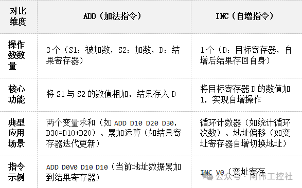
 Collaborative Logic in the Summation Case: Taking D0-D9 as an ExampleWhen summing the 10 continuous registers from D0 to D9, ADD and INC need to work together in a loop logic of “accumulate-offset-accumulate”:
- Initialization Preparation
-
Zero the result register D10 (
<span>MOV K0 D10</span>), initialize the offset register V0 to 0 (<span>MOV K0 V0</span>), at this point D0V0 points to the first data register D0.
<span>ADD D0V0 D10 D10</span>, adding the value of the current address D0V0 (first loop is D0) to the result register D10, storing the result back in D10. For example, if D0=5 and D10=0, then after the operation D10=5..<span>INC V0</span>, incrementing the value of the offset register V0 by 1 (from 0→1→2…→9), dynamically switching the address pointed to by D0V0 (D0→D1→D2…→D9)..Key Logic Summary: The ADD instruction achieves value accumulation through “current data + accumulated sum = new accumulated sum,” while the INC instruction achieves automatic address switching through the increment of the offset register, forming a closed loop of “data processing-address updating,” which is the core mechanism of loop summation. Instructions Usage Notes
-
Carry Handling in ADD: If the result exceeds the register capacity during accumulation (e.g., 16-bit register maximum value 32767), the carry flag M8022 will be set to 1, and overflow handling must be considered in the program..
-
Circular Nature of INC: The INC instruction is a circular counter; when the register value reaches the upper limit, it will restart from the minimum value (e.g., 16-bit unsigned number from 65535→0). When designing loops, the termination condition must be controlled through comparison instructions (e.g., CMP)..
By combining ADD and INC, not only can the summation of D0-D9 be efficiently completed, but it can also be extended to summation operations for larger ranges such as D0-D99, making it a highly flexible combination tool in PLC data processing.
04D0-D9 Summation Case: Complete Implementation of Summing 10 Numbers
 Loop Logic AnalysisThe loop logic for summing D0-D9 using offset register V0 in PLC essentially transforms the scattered register addresses into a continuous accessible loop process through the “incrementing offset value – address offset – data accumulation” linkage mechanism. Below, we will break down the core principles with a specific case:Core Execution Process
-
Initialization: Set the offset register V0 to 0 (starting offset), and zero the result register D10 (initial accumulation value).
-
Loop Control: Use the FOR instruction to set the loop to 10 times (corresponding to 10 data from D0-D9).
-
Address Offset: Each loop accesses the current offset address through
<span>D0V0</span>(e.g., when V0=0, it is D0; when V0=1, it is D1). -
Accumulation Operation: Use the ADD instruction to accumulate the current address data into D10, while incrementing V0 by 1 using the INC or ADD instruction.
-
Termination Condition: When V0 increments from 0 to 9, completing 10 loops, D10 stores the total sum.
Key Loop Node Demonstration
Taking the first and last executions in the loop as examples, we will intuitively demonstrate the dynamic relationship between V0, addresses, and accumulation results:First Loop (V0=0)
-
Address Calculation:
<span>D0V0 = D0+0 = D0</span>(offset value 0 corresponds to the first address D0). -
Accumulation Operation:
<span>ADD D10, D0, D10</span>→ D10 updates from initial 0 to the value of D0. -
V0 Increment: After executing
<span>INC V0</span>, V0 becomes 1, pointing to the next address D1.
Tenth Loop (V0=9)
-
Address Calculation:
<span>D0V0 = D0+9 = D9</span>(offset value 9 corresponds to the last address D9). -
Accumulation Operation:
<span>ADD D10, D9, D10</span>→ D10 accumulates the value of D9, at this point<span>D10 = D0+D1+...+D9</span> -
Loop End: After incrementing, V0 becomes 10, reaching the loop count limit (10 times), exiting the loop.
Loop Count – Address – V0 Value Correspondence Table
This table clearly presents the interrelationship among the three, helping to understand how the offset register achieves “dynamic jumping” of addresses: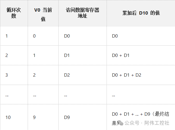 Through the above mechanism, offset register V0 acts like a “dynamic pointer” under the control of the FOR loop, sequentially traversing the addresses D0-D9, achieving efficient programming without needing to repeatedly write 10 ADD instructions. This logic is not only applicable to summation scenarios but can also be extended to batch data transfer, comparison, and other continuous address operations.
  Ladder Diagram and Result VerificationIn the application of summation using offset register V0 in PLC, the ladder diagram is the core carrier for implementing logical control, while result verification is the key step to ensure program reliability. Below, we will break down the complete process from startup execution to result confirmation, combining specific logical structures and practical methods.
Core Logic Analysis of the Ladder Diagram
The design of the ladder diagram must meet the requirements of “single trigger, periodic completion, and precise accumulation,” and its typical structure includes three major modules:1. Startup and Initialization PhaseUsing X0 as the startup signal, when X0 is connected, the program is triggered to execute. To avoid accumulation errors, two initialization tasks must be completed first:
-
By
<span>MOV K0 V0</span>, zero the offset register V0 to ensure addressing starts from D0; -
By
<span>MOV K0 D10</span>, zero the result register D10 to eliminate interference from historical data..
2. FOR-NEXT Loop Execution PhaseThe core logic is implemented through the FOR-NEXT instruction for 10 cycles of accumulation, with the key code as follows:
LD X0              ; Triggered by startup signal
MOV K0 V0           ; Zero V0 (initial offset 0)
MOV K0 D10          ; Zero result register
FOR K10             ; Loop 10 times (corresponding to D0-D9, a total of 10 registers)
ADD D10 D0V0 D10    ; D10 += D0V0 (current address data accumulation)
INC V0              ; V0 increments by 1 (offset +1, pointing to the next register)
NEXT
When V0 increments from 0 to 9,
<span>D0V0</span>sequentially accesses D0, D1, …, D9, achieving continuous accumulation of 10 registers [^Mitsubishi FOR loop case].
3. Anti-Repetition Execution MechanismIt is important to note that the FOR-NEXT instruction completes all 10 cycles within a single scan cycle. To avoid continuous connection of X0 leading to multiple cycles of repeated accumulation, it is common in practical applications to use edge-triggered (such as the Pulse instruction for X0) or intermediate relays (such as M0) to control, ensuring the program executes only once. Key Considerations: The loop count must strictly match the number of registers. If the loop count is set to K10, it corresponds to 10 data from D0-D9; if mistakenly set to K11, it will incorrectly accumulate data from D10, leading to result deviations..
Result Verification Practical Methods
The correctness of the program must be verified through dual verification of “manual calculation-software monitoring”:1. Manual Summation Baseline CalculationFirst, assign test data to D0-D9, for example:
-
D0=10, D1=15, D2=12, D3=16, D4=20
-
D5=8, D6=25, D7=18, D8=5, D9=22
Manual calculation of the total: 10+15+12+16+20+8+25+18+5+22=151.
2. PLC Monitoring Software VerificationUse programming software (such as GX Works2) to monitor the value of D10 online:
-
After triggering X0, observe whether D10 updates in real-time to 151;
-
If intermediate processes need to be checked, monitor the changes in V0 (0→9) and the corresponding address switching of
<span>D0V0</span>, confirming that each register data is correctly accumulated..
Quick Verification Technique: Use the “extreme value testing method”—set all D0-D9 to 0 to verify if D10 is 0; set all to 1 to verify if D10 is 10, quickly troubleshooting initialization or loop logic errors. Through the structured design of the ladder diagram and scientific verification methods, it can be ensured that offset register V0 achieves efficient and accurate data processing in summation scenarios, laying the foundation for complex PLC control logic.
05D0-D99 Summation Extension: Optimized Solution for Summing 100 Numbers
 Loop Count and Address RangeIn PLC program design, when implementing the summation operation for the 100 data registers from D0-D99, the setting of the loop count and control of the address range are core steps to ensure the program runs accurately. First, the loop count must be clearly set to K100, meaning the FOR-NEXT loop will execute 100 times—this value not only meets the range of loop counts allowed by the FOR instruction (1~32767) but also directly corresponds to the access needs of 100 continuous data from D0 to D99.
Implementation Mechanism of Dynamic Address Access
In this process, the offset register V0 acts as a “dynamic pointer.” We set the initial value of V0 to 0, and each loop increments it (e.g., INC V0) from 0 to 99. At this point, accessing the address D0V0 will achieve dynamic offset as V0 changes: when V0=0, D0V0 points to D0; when V0=1, it points to D1… until V0=99, pointing to D99, perfectly covering the address range of 100 continuous data registers. This mechanism is like flipping through a 100-page book in order, with V0 acting as the page number, flipping from page 0 (D0) to page 99 (D99), ensuring no data is missed.
Key Differences from “10 Numbers” to “100 Numbers”
Comparing the common “D0-D9 summation of 10 numbers” scenario, the core difference between the two lies in the difficulty of controlling address boundaries. In summing 10 numbers, the maximum value of V0 is 9, and even a slight deviation is unlikely to exceed the conventional range of D registers; however, when extending to 100 numbers, V0 needs to stop precisely at 99. If due to program anomalies (such as an INC instruction failure), V0 exceeds 99, it may access unknown areas beyond D100, leading to data errors or even program crashes. Address Out-of-Bounds Protection Technique: Add a CMP V0 K99 M0 comparison instruction in the loop body. When V0 equals 99, M0 is set to 1; if V0 unexpectedly exceeds 99, M0 remains 0 and triggers an alarm or loop termination logic. This “double insurance” can effectively enhance program robustness, especially suitable for the complex operating environments in industrial sites. In actual programming, the matching of loop counts and address ranges must follow the principle of “Loop Count = End Address – Start Address + 1. For example, the starting address for D0-D99 is 0, and the ending address is 99, so the loop count is 99 – 0 + 1 = 100 times. This logic also applies to batch operations in other continuous address areas. By reasonably setting loop parameters and address offsets, combined with boundary check instructions, the summation task for 100 data can be efficiently and safely completed. Overflow Handling and 32-bit OperationsIn PLC data processing, register overflow is a common hidden danger leading to calculation errors. Taking this summation of 100 numbers as an example, if each data is 1000, the total will reach 100000, far exceeding the maximum storage range of a 16-bit register (signed -32768~32767, unsigned 0~65535). At this point, a 32-bit operation architecture must be adopted, which can handle a register range of ±2147483647, sufficient to meet the accumulation needs of most industrial scenarios.
32-bit Operation Implementation Plan
32-bit data must be stored in two consecutive 16-bit registers (e.g., D10 for low 16 bits, D11 for high 16 bits), and a dedicated 32-bit addition instruction DADD must be used for accumulation. The core logic is to add the source data addressed by the offset (D0V0) to the 32-bit result register (D10-D11), with the instruction format as:<span>DADD D0V0 D10 D10</span> This instruction will automatically handle the collaborative operations of D10 (low word) and D11 (high word), ensuring the integrity of the 32-bit data. Key Code Example (100 times loop accumulation):
FOR K100            ; Loop 100 times (traversing D0~D99)
DADD D10 D0V0 D10   ; 32-bit addition: (D0+V0) value accumulates to D10-D11
INC V0              ; Increment offset register V0 (offset 0→99)
NEXTNote: The 16-bit addition instruction (such as ADD) will overflow immediately if the result exceeds 32767, while DADD can support a maximum accumulation value of 2147483647..
Overflow Detection and Alarm Mechanism
Even with 32-bit operations, if the accumulation value exceeds ±2147483647, it will still overflow. The PLC monitors the overflow status in real-time through the M8022 carry flag: when the operation result exceeds the 32-bit range, M8022 is automatically set to 1. At this point, it can link to external alarm devices to prompt the user to check the data source. A typical handling code is as follows:<span>LD M8022 OUT Y0</span> which outputs a high level at the Y0 port when an overflow occurs, driving an indicator light or buzzer alarm. In actual debugging, attention must also be paid to the range limitations of the offset register itself: the 16-bit V/Z registers, when used alone, cannot exceed an offset of ±32767. If a larger addressing range is needed (e.g., offset >255), V (high 16 bits) and Z (low 16 bits) must be combined into a 32-bit offset register to avoid address access errors. Through the three-layer protection of “32-bit register storage + dedicated operation instructions + flag detection,” the risk of overflow during the accumulation process can be effectively avoided, ensuring the accuracy and reliability of data processing in industrial control.
06Practical Application Scenarios: From Cases to Industrial Sites
As a “flexible tool” in PLC programming, offset register V0 demonstrates strong adaptability in industrial sites. Whether for batch data processing, multi-device compatibility, or rapid model switching needs, its address offset characteristics can achieve the effect of “one-time programming, multi-scenario reuse.” The following three core scenarios will reveal how it simplifies complex control logic: 1. Production Line Data Collection: Real-time Summary of Output from 100 WorkstationsIn automotive parts assembly lines or electronic component production lines, output data from 100 workstations is usually stored in D0-D99 registers. Traditional programming requires repeating 100 addition instructions, while using the V0 offset register combined with loop instructions can compress the program to under 10 lines.Core Logic: Initialize V0=0, and accumulate D0V0 data to D100 through a FOR loop (K100 times), with the final result directly pushed to the HMI panel to display total output.Simplified Program Snippet:
MOV K0 V0           // Initialize offset value
FOR K100            // Loop 100 times
ADD D0V0 D100 D100  // Accumulate D0~D99 data to D100
INC V0              // Increment offset by 1
NEXT // End of loop Advantages: Whether adding workstations or adjusting addresses, only the loop count needs to be modified, avoiding the need to modify 100 fixed address instructions one by one. This method has been validated in a certain power battery production line, achieving automatic hourly output statistics by dynamically accessing D0-D99 sensor data, improving program maintenance efficiency by 80%.  2. Equipment Status Monitoring: Parameter Compatibility Solution Across ModelsFood packaging machines often need to adapt to different specifications of heating modules (for example, the number of temperature sensors for a film sealing machine may be 8 or 16). Fixed address programming requires writing separate programs for each model, while V0 can dynamically read temperature (D0V0), pressure (D1V0), and other parameters by setting the offset through a dial switch.Application Example: A certain production line runs both model A and model B packaging machines simultaneously, with model A’s temperature stored in D100-D107 and model B’s in D200-D207.Simplified Program Snippet:
MOV K100 V0         // Select model A with dial switch, V0=100
LD M0               // Startup signal
MOV D0V0 D500       // Read model A's temperature 1 (D100) to D500
MOV D1V0 D501       // Read model A's pressure (D101) to D501
// When switching to model B, only need to change to MOV K200 V0 Advantages: One program adapts to the entire series of devices, and when switching models, there is no need to modify the code, only adjusting the initial value of V0. A certain beer filling line adopted this scheme, reducing equipment switching debugging time from 4 hours to 15 minutes, and supporting seamless integration of future new device models.  3. Recipe Parameter Calling: Rapid Model Switching for Screw Machines with 50 ProductsIn three-axis gantry automatic screw machines, each product corresponds to the X/Y/Z coordinates of 50 screw holes (for example, product A is stored in D100-D149, product B in D150-D199). Traditional programming requires writing independent calling logic for each product, while V0 can dynamically locate parameter areas based on product numbers.Core Operation: By selecting product number N through HMI, calculate V0=50*N, allowing access to D100V0 (X coordinate), D200V0 (Y coordinate), and other parameters.Simplified Program Snippet:
MOV K5 V0           // Select the 5th product (V0=5*10=50, assuming each group has 10 parameters)
DMOV D100V0 D300    // Read X coordinate (D150) to the motion controller
DMOV D200V0 D302 // Read Y coordinate (D250) to the motion controller Advantages: When adding new products, there is no need to modify the program, only expanding the parameter storage area in the D zone, achieving “teaching is effective immediately” for flexible production. A certain consumer electronics factory’s screw machine production line applied this scheme, reducing product switching time from 2 hours to 5 minutes, increasing the number of supported SKUs from 10 to 50, and reducing program maintenance by 90%.  Conclusion: The “One-Time Programming” Philosophy of Offset RegistersFrom data collection to parameter calling, the V0 offset register breaks the shackles of traditional fixed address programming through “dynamic addressing.” Its core value lies in:replacing hard coding with variable offsets, upgrading programs from “customized for a single scenario” to “general for a class of scenarios.” Whether it is the summation of 100 workstations, compatibility of 10 devices, or switching among 50 products, it can be achieved with just a few lines of core code—this is a reflection of the programming wisdom of “cost reduction and efficiency enhancement” in industrial automation.
07Conclusion: The Efficiency Revolution of Offset Register V0
In the field of PLC programming, the emergence of offset register V0 marks a revolutionary shift from “repetitive coding” to “one-time programming.” Through the dynamic address access mechanism, it transforms control logic that originally required hard coding line by line into reusable and scalable flexible programs, bringing a qualitative change in efficiency to industrial automation control.Core Efficiency Breakthrough: Three Dimensions Restructuring PLC Programming Model
-
Code Volume Reduced by 90%: Traditional summation of 100 numbers from D0-D99 requires writing 100 ADD instructions, while using V0 offset combined with FOR-NEXT loops, only 10 lines of code are needed to achieve batch data accumulation, reducing program steps by over 50%, completely eliminating repetitive labor..
-
Dynamic Adaptation to Production Changes: When the data volume increases from 10 to 100, there is no need to modify the core logic, only adjusting the loop count parameter, combined with a dial switch or upper computer to quickly switch the data processing range, compressing changeover debugging time from half a day to a few minutes..
-
Significantly Reduced Maintenance Difficulty: The address offset logic is uniformly managed through the V0 variable, allowing intuitive tracking of data flow during fault troubleshooting, avoiding the need to check fixed addresses line by line in hundreds of lines of repeated code, enabling even non-professionals to quickly locate issues..
This design philosophy of “separating data from logic” not only simplifies the programming process but also endows PLC programs with unprecedented flexibility. In industrial changeover scenarios, by managing recipe parameters through V0, enterprises can reduce reliance on specialized programming personnel; in multi-channel data collection, combined with expanded SRAM cards, 32-bit offsets support large-capacity file register access, meeting the demands of smart manufacturing for large memory data processing. Looking ahead, the integration of offset register V0 with the industrial internet will unleash even greater potential. By remotely modifying the V0 offset or loop count, online adjustments to production parameters can be achieved without stopping to rewrite programs, perfectly echoing the core proposition of “flexibility upgrade in industrial automation” introduced in the beginning. From batch data processing on production lines to dynamic parameter configuration in smart factories, V0 is driving PLC programming from the “hard coding era” to a “flexible new era” with the simplest instruction combinations (MOV, INC, ADD).
08Appendix: Case Programs and Image Descriptions
 1. D0-D9 Summation Program Template (with Detailed Comments)Below is a reusable ladder diagram program template for summing D0-D9 based on offset register V0, including key instruction comments and debugging points:
// 1. Offset Register Initialization (Triggered by X000 Rising Edge)
LD X000          // Detect rising edge of startup signal
MOV K0 V0        // Assign constant 0 to offset register V0, pointing D0V0 to D0 initially
MOV K0 D1        // Clear accumulation register D1 (initial value 0)

// 2. FOR Loop Structure (Loop 10 times, covering D0-D9)
FOR K10          // Light green FOR box: Set loop count to 10 (corresponding to D0-D9, a total of 10 registers)
  ADD D0V0 D1 D1 // Orange ADD box: Accumulate the value of D0V0 (first is D0, after V0 increments, it will be D1-D9) with D1, storing the result back in D1
  INC V0         // Increment offset register V0 by 1 (pointing to the next data register)
NEXT             // End of loop

// 3. Result Storage and Verification
LD M8000         // Constant ON contact, continuously monitor the result
MOV D1 D10       // Store the final accumulated sum in D10 (reference result: when D0-D9 are 0-9, D10=45)
Debugging Tips:
-
Before triggering X000, ensure D0-D9 have been assigned values (suggest pre-setting 0-9 for verification);
-
If the result is abnormal, first check whether V0 initialization is zero (MOV K0 V0) and whether the FOR loop count is K10..
 2. Key Elements of the Ladder Diagram
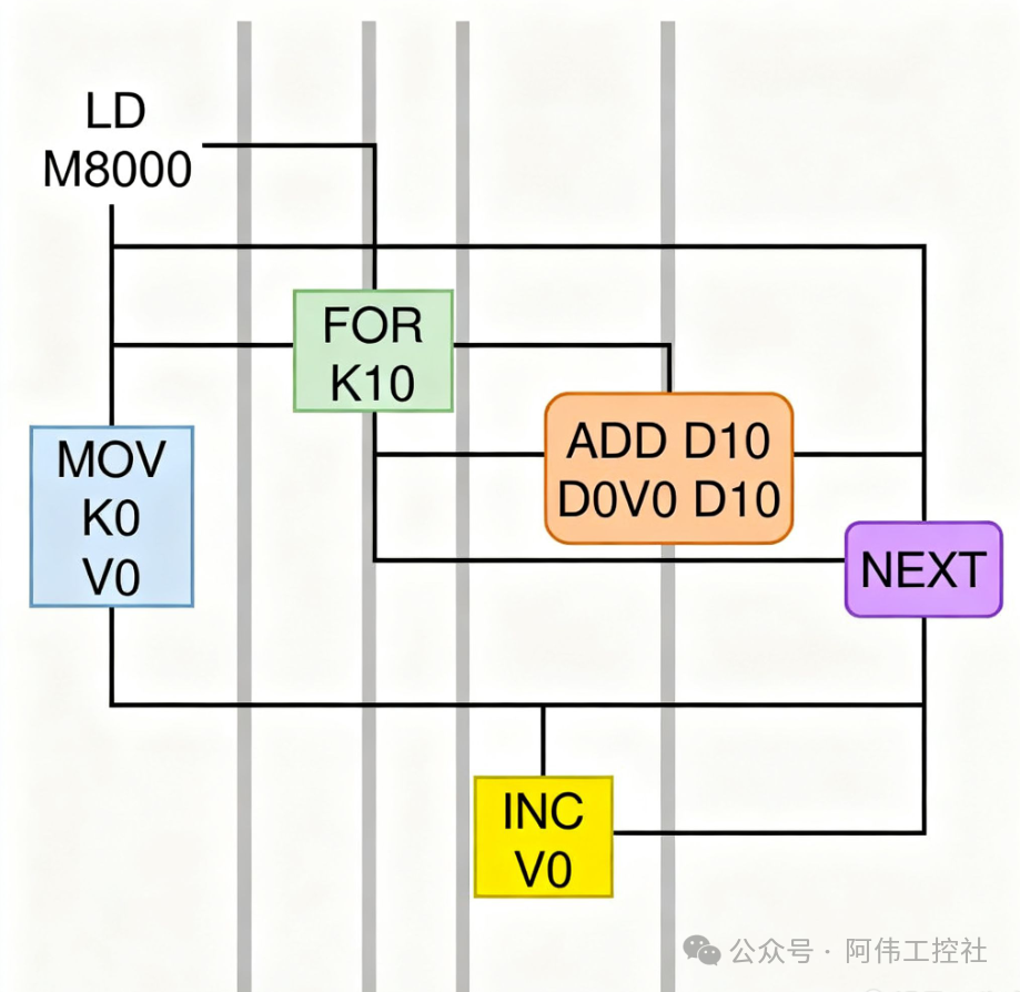 In the ladder diagram, pay special attention to the following visual identifiers and logical relationships:
-
Light Green FOR Box: Located in the second line of the program, internally labeled “K10,” connected to the rising edge signal of X000 on the left, and linking to the loop body (ADD instruction and V0 increment instruction) on the right, visually displaying the execution range of the loop.
-
Orange ADD Box: The core calculation unit within the loop body, with internal parameters “D0V0 D1 D1” indicating “source operand 1 (offset addressing) + source operand 2 (accumulated sum) → target operand (update accumulated sum),” with an orange arrow pointing to the NEXT instruction below the box, indicating the flow of the loop.
-
Offset Register Chain: As the value of V0 increments from 0 to 9, D0V0 sequentially points to D0→D1→…→D9, with dashed lines on the right side of the ladder diagram indicating the mapping relationship “V0=0→D0” “V0=1→D1,” assisting in understanding the address offset logic.
 3. Working Diagram of Offset Register V0
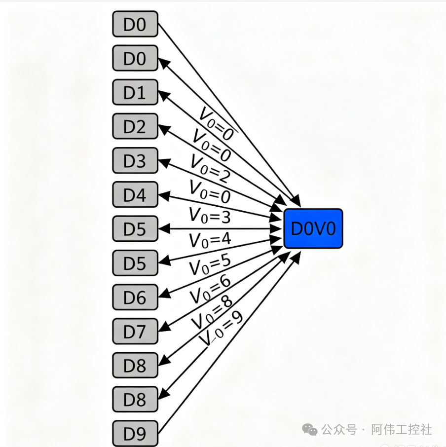 The diagram uses a layered structure to show the dynamic relationship between V0 and data registers:
-
Bottom Layer: 10 data registers D0-D9 arranged horizontally, with each register labeled with its memory address (e.g., D0: 0x0000, D1: 0x0001, etc.).
-
Middle Layer: The offset register V0 exists as an orange slider, initially pointing to D0 (V0=0), gradually moving right as the loop executes, with the current value (0→1→…→9) displayed next to the slider.
-
Top Layer: The accumulated sum D1 dynamically changes as a bar graph, increasing in height after each ADD instruction execution, ultimately stopping at the corresponding total (e.g., when summing 0-9, the height of the bar graph corresponds to 45).
Core Principle: The offset register V0 achieves batch access to continuous address space by changing the combination of “base address (D0) + offset (V0 value),” replacing the redundant programming of 10 repeated ADD instructions.. 4. Common Instruction Quick Reference Table
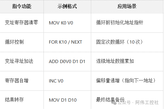
Note: During actual debugging, the “monitoring mode” of PLC programming software can be used to observe the changes in V0 and the accumulation process of D1 in real-time, quickly locating logical errors.
 Phone Number: 13147077956 Scan the QR code Get the materials