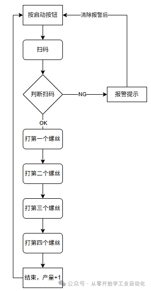
 This practical project shares how to start a project from scratch using a common screw tightening machine. The content will be presented based on a consistent framework that is easy to understand. Based on Mitsubishi, Weintek touch screens, Keyence barcode scanners, and C# host computer, we will implement an automated screw tightening traceability system that records the assembly time and results for each phone’s screws.The entire project is divided into 5 chapters, and today we will discuss section (3):(1) Electrical Preliminary Design: Scheme, Requirements, I/O Table, Selection,PLC & Host Computer Interaction Protocol; (2) Host Computer Design: Develop C# WinForms software to achieve barcode scanner SN code reading, PLC status interaction, and production data storage and query;(3)PLC Program Design: Write ladder diagrams using GX Works2;(4) Touch Screen Design: Use EasyBuilder Pro to create the touch screen interface;(5) Debugging and Summary: Connect the host computer to the physical PLC and connect a virtual barcode scanner (can be simulated via serial port) for our action debugging.1. Device Action Flow and Program Framework Overview When writing a program, we cannot just take the scheme and immediately start opening the software to write while thinking. We need to plan the program flow in advance. Generally, companies have their own program frameworks; here we will simply conceptualize one ourselves.1. Clarify the action flow
 2. Program Framework ConceptualizationThis program is implemented in a modular way, and the program is relatively simple. We divide it into 5 modules.Module Definitions:
- Parameter Restore to Factory Settings.
- Whole Machine Initialization Module.
- Manual Module.
- Automatic Module.
- Alarm Module.
3. Create Program Since we previously selected the FX3U-32MT/ES-A, we will choose the FX3U/FX3UC model here, select simple project type, and use ladder diagram as the programming language. Remember to check “Use Tags” so that our program can be processed in blocks more conveniently.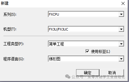 4. Address Area DivisionWe commonly use several components such as D, M, X, Y, T. Allocate a separate area for different modules to make the program look more standardized, and it will be more convenient for us to view and write.First, we need to familiarize ourselves with which categories these registers belong to, which can be viewed in: Project –> Parameters –> PLC Parameters –> Soft Component Settings. See the image below:
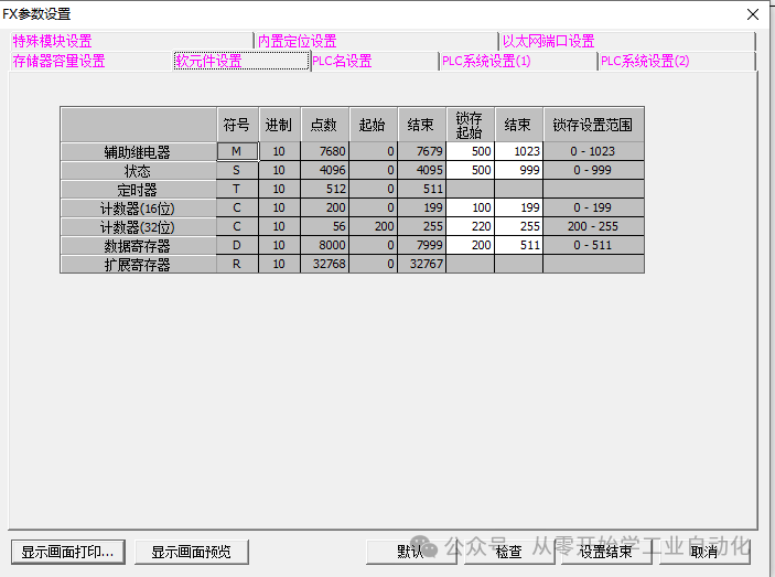 Regarding writing PLC logic flow, there are generally two common methods:
- Using basic contacts M step by step.
- Using a D=K0, K1, K2 method.
I prefer using the D method, so we will plan according to this.Flow Control Register D Division (with power-off retention):Whole Machine Initialization Module: D200-D209Manual Module: D210-D219Automatic Module: D220-D229Alarm Module: Alarms generally do not have a flow, so no allocation here.Parameter Register D Division (with power-off retention):Overall not subdivided, uniformly using D300-D399 range.M Division:Output Y Conversion: M0-M19, corresponding to Y0-Y17, for easy memory.Control Signals: M20-M29, such as Start, Stop, Reset, etc.Manual Control: M30-M49.Parameter Restore to Factory Settings: M50Production Zeroing: M51Host Computer Communication: M100-M149, already divided in the first chapter.Alarm Flags: M150-M169.Automatic Module Use: M200-M249 Others cannot be fully estimated in advance, and adjustments will be made based on actual conditions when writing the program.5. Program Writing(1) Add IO Comments. Batch copy or input comments individually after X0 is fine.The same applies to Y.(2) Establish Program ModulesRight-click on the program location –> New Data
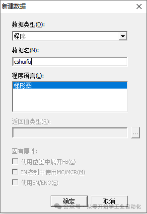
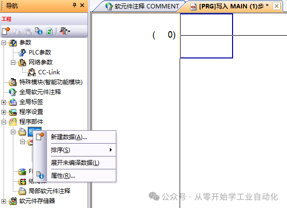 Input data names; since there are too many Chinese characters, it is recommended to use lettersParameter Restore to Factory Settings – cshuifuWhole Machine Initialization Module – cshManual Module – sdAutomatic Module – zdAlarm Module – bj
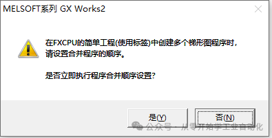
 Confirm, a prompt will pop up; click No, as this project does not require this setting for now.
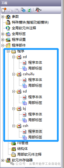
 Similarly, create the other 4, changing the main program to the automatic module, resulting in the following:
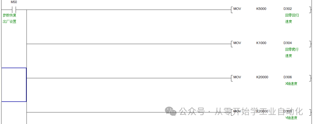
 (3) Write Program Contenta. Parameter Restore to Factory Settings ProgramSince whether it is the first machine or a replicated machine, each parameter needs to be set to a default value; otherwise, it can easily cause problems that are hard to find. I believe everyone has encountered this pitfall, so our program must have a one-click restore to factory parameter settings function.Let’s list the parameters:Total Production: D300 (D100 was used in the first chapter; for power-off retention, we changed it to D300 double word)Return to Zero Speed: D302 (For demonstration convenience, all three axes default to 1 pulse for the same distance)Return to Zero Creep Speed: D304X Axis Speed: D306Y Axis Speed: D308Z Axis Speed: D310Screw Hole 1 – X Axis Position (pulses): D312Screw Hole 1 – Y Position (pulses): D314Screw Hole 1 – Z Axis Position (pulses): D316Screw Hole 2 – X Axis Position (pulses): D318Screw Hole 2 – Y Position (pulses): D320Screw Hole 2 – Z Axis Position (pulses): D322Screw Hole 3 – X Axis Position (pulses): D324Screw Hole 3 – Y Position (pulses): D326Screw Hole 3 – Z Axis Position (pulses): D328Screw Hole 4 – X Axis Position (pulses): D330Screw Hole 4 – Y Position (pulses): D332Screw Hole 4 – Z Axis Position (pulses): D334Safety Position – X Axis Position (pulses): D336Safety Position – Y Position (pulses): D338Safety Position – Z Position (pulses): D340Note: Pulse values are generally large, so all the above D are using 32-bit double words, which will occupy two D.The parameters are basically listed, and we will initialize them in the program. Double-click cshuifu -> program body to start programming.
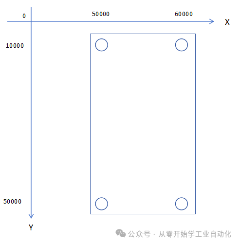
 Below is a rough sketch of a coordinate system (abstract diagram!!!), so that everyone can see the coordinates and know how much to input for parameter initialization. The following pulse numbers are the designed positions, with the Z-axis height designed as 60000 pulses.
 Finally, let M50 reset itself.
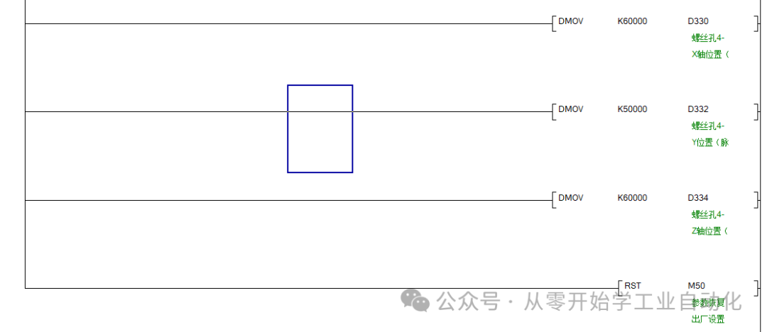 At this point, our parameter initialization program is complete.The entire program is too extensive, and I realize this article will be too long. I will complete the thought process and then rewrite an article focusing solely on the program, attaching the source code for download in the public account, just like the previous source code for the host computer. I apologize for that.

 Today’s sharing ends here, and I will continue with the complete PLC program sharing and release.If anyone has any questions or needs to discuss, feel free to leave a message. If you like it, please give a thumbs up or save it.Below are my other technical articles that may provide assistance:Beginner Project: Automated Screw Tightening Machine – C#, PLC, Touch Screen Practical Application (1/5): Electrical Preliminary DesignBeginner Project: Automated Screw Tightening Machine – C#, PLC, Touch Screen Practical Application (2/5): C# WinForms Host Computer DesignIndustrial Automation: PLC, HMI Manuals and Comprehensive Industrial Control Software (with reliable download channels)