We designed a subroutine for processing analog outputs, which can convert engineering values into analog output values, and includes output limits, gain adjustments, and alarm functions.Features:
-
Converts engineering values (real numbers) into integers ranging from 0 to 27648 for analog output.
-
Allows setting of gain and offset to adjust output characteristics.
-
Allows setting of upper and lower limits to restrict the output range.
-
Generates an alarm signal when the engineering value exceeds the output range.
Subroutine Parameters:IN:Eng_Value : REAL Engineering value, the physical quantity to be output (e.g., pressure, temperature, etc.)Gain : REAL Gain, default 1.0Offset : REAL Offset, default 0.0Out_Min : REAL Minimum engineering value (corresponding to analog output 0)Out_Max : REAL Maximum engineering value (corresponding to analog output 27648)Clamp_Min : REAL Minimum output clamp value (engineering units), if output is below this value, it clamps and alarmsClamp_Max : REAL Maximum output clamp value (engineering units), if output is above this value, it clamps and alarmsOUT:AQ_Out : INT Analog output value (0-27648)Clamp_Low_Alarm : BOOL Alarm for output value clamped at minimumClamp_High_Alarm: BOOL Alarm for output value clamped at maximumTEMP:Temp_Real : REAL Temporary calculation variableLogical Analysis:
-
First, multiply the engineering value by the gain and add the offset.
-
Then limit the result between Clamp_Min and Clamp_Max; if clamped, set the corresponding alarm position.
-
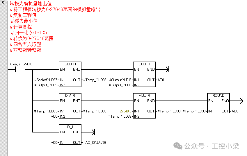
Convert the clamped engineering value into an integer ranging from 0 to 27648.
Note: We assume the range of the analog output module is 0-27648, corresponding to 0-10V or 0-20mA, etc.
Conversion Formula:Normalized Value = (Eng_Value * Gain + Offset – Out_Min) / (Out_Max – Out_Min)Then limit the normalized value between 0.0 and 1.0, and multiply by 27648 to get the integer output.
However, we first perform gain offset, then clamp, and finally convert to output value..
Steps:
-
Calculate: Temp_Real = Eng_Value * Gain + Offset
-
Clamp: If Temp_Real < Clamp_Min, output Clamp_Min and set Clamp_Low_Alarm; if Temp_Real > Clamp_Max, output Clamp_Max and set Clamp_High_Alarm.
-
Convert the clamped value to the output range: AQ_Out = (Temp_Real – Out_Min) * (27648.0 / (Out_Max – Out_Min)), then round.
Note: If Out_Max equals Out_Min, avoid division by zero errors, so the program must include checks.
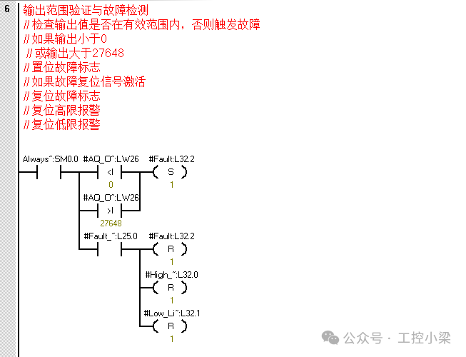
Below is the ladder diagram program.Here is a fully functional analog output processing subroutine that supports gain adjustment, output limits, alarm monitoring, and manual/automatic switching functions.Create SubroutineSubroutine Name:Analog_Output_ControlVariable Definitions
| Variable Type | Variable Name | Data Type | Description |
|---|---|---|---|
| IN | Auto_Manual | BOOL | Automatic/manual mode switch (1=automatic) |
| IN | Setpoint_Manual | REAL | Manual setpoint (0.0-1.0 or engineering value) |
| IN | Setpoint_Auto | REAL | Automatic setpoint (0.0-1.0 or engineering value) |
| IN | Output_Min | REAL | Minimum output value (engineering units) |
| IN | Output_Max | REAL | Maximum output value (engineering units) |
| IN | Gain | REAL | Gain coefficient (default 1.0) |
| IN | Offset | REAL | Offset (default 0.0) |
| IN | Fault_Reset | BOOL | Fault reset signal |
| OUT | AQ_Output | INT | Analog output value (0-27648) |
| OUT | Output_Eng | REAL | Output value in engineering units |
| OUT | High_Limit_Alarm | BOOL | Output exceeds upper limit alarm |
| OUT | Low_Limit_Alarm | BOOL | Output exceeds lower limit alarm |
| OUT | Fault | BOOL | Output fault status |
| TEMP | Temp_Value | REAL | Temporary calculation variable |
| TEMP | Scaled_Output | REAL | Scaled output value |
Program Logic
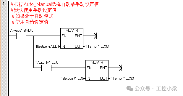
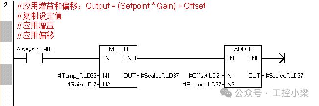
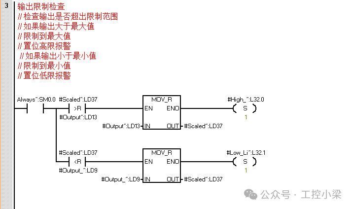
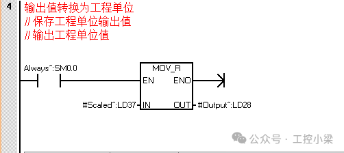
Appendix: Statement Table Program
LD Always_On:SM0.0
MOVR #Setpoint_Manual:LD1, #Temp_Value:LD33
A #Auto_Manual:L0.0
MOVR #Setpoint_Auto:LD5, #Temp_Value:LD33
LD Always_On:SM0.0
MOVR #Temp_Value:LD33, #Scaled_Output:LD37
AENO
*R #Gain:LD17, #Scaled_Output:LD37
AENO
+R #Offset:LD21, #Scaled_Output:LD37
LD Always_On:SM0.0
LPS
AR> #Scaled_Output:LD37, #Output_Max:LD13
MOVR #Output_Max:LD13, #Scaled_Output:LD37
AENO
S #High_Limit_Alarm:L32.0, 1
LPP
AR< #Scaled_Output:LD37, #Output_Min:LD9
MOVR #Output_Min:LD9, #Scaled_Output:LD37
AENO
S #Low_Limit_Alarm:L32.1, 1
LD Always_On:SM0.0
MOVR #Scaled_Output:LD37, #Output_Eng:LD28
LD Always_On:SM0.0
LPS
MOVR #Scaled_Output:LD37, #Temp_Value:LD33
AENO
-R #Output_Min:LD9, #Temp_Value:LD33
AENO
MOVR #Output_Max:LD13, AC0
-R #Output_Min:LD9, AC0
LRD
/R AC0, #Temp_Value:LD33
AENO
*R 27648.0, #Temp_Value:LD33
AENO
ROUND #Temp_Value:LD33, AC0
LPP
DTI AC0, #AQ_Output:LW26
LD Always_On:SM0.0
LPS
LDW< #AQ_Output:LW26, 0
OW> #AQ_Output:LW26, 27648
ALD
S #Fault:L32.2, 1
LPP
A #Fault_Reset:L25.0
R #Fault:L32.2, 1
R #High_Limit_Alarm:L32.0, 1
R #Low_Limit_Alarm:L32.1, 1
Function Description
-
Mode Selection
-
Automatic mode: Uses the externally provided Setpoint_Auto as the setpoint
-
Manual mode: Uses the operator-set Setpoint_Manual as the setpoint
Signal Processing
-
Applies gain and offset: Output = (Setpoint * Gain) + Offset
-
Gain: Amplifies or reduces the input signal
-
Offset: Adjusts the reference point of the output signal
Output Limiting
-
Ensures the output value is within the Output_Min and Output_Max range
-
Triggers corresponding alarms and limits output when exceeded
Engineering Value Conversion
-
Converts output values to engineering units for monitoring
Analog Output Conversion
-
Converts engineering values to integers in the range of 0-27648
-
Applicable to S7-200 SMART analog output modules
Fault Detection and Alarming
-
Detects whether the output value exceeds the valid range (0-27648)
-
Provides high and low limit alarm signals
-
Supports fault reset functionality
Call Example
// Call the analog output control subroutine in the main program
LD SM0.0
CALL Analog_Output_Control
Auto_Manual := M0.0 // Automatic/manual mode selection
Setpoint_Manual := VD100 // Manual setpoint (0.0-100.0%)
Setpoint_Auto := VD200 // Automatic setpoint (0.0-100.0%)
Output_Min := 0.0 // Minimum output value (0%)
Output_Max := 100.0 // Maximum output value (100%)
Gain := 1.2 // Gain coefficient 120%
Offset := 0.0 // Offset 0%
Fault_Reset := I0.0 // Fault reset button
AQ_Output => AQW0 // Analog output channel
Output_Eng => VD300 // Output value in engineering units
High_Limit_Alarm => Q0.0 // High limit alarm indicator
Low_Limit_Alarm => Q0.1 // Low limit alarm indicator
Fault => Q0.2 // Fault indicator
Usage Notes
-
Gain and Offset Settings
-
Gain is typically set to 1.0 and can be adjusted as needed
-
Offset is used to calibrate the zero point of the output signal
Output Limiting
-
Set appropriate output limits based on actuator capabilities
-
Avoid setting overly strict limits that may degrade control performance
Fault Handling
-
Add fault handling logic in the program, such as switching to a safe state during faults
-
Regularly check the status of the output module to ensure proper operation of the analog output
Engineering Units
-
Select appropriate engineering units based on actual application (e.g., percentage, pressure, temperature, etc.)
-
Ensure all parameters use the same engineering units
This subroutine provides complete analog output processing functionality and can be directly integrated into control systems, adapting to different actuators and process requirements through parameter adjustments.
Mode Selection
Automatic mode: Uses the externally provided Setpoint_Auto as the setpoint
Manual mode: Uses the operator-set Setpoint_Manual as the setpoint
Signal Processing
Applies gain and offset: Output = (Setpoint * Gain) + Offset
Gain: Amplifies or reduces the input signal
Offset: Adjusts the reference point of the output signal
Output Limiting
Ensures the output value is within the Output_Min and Output_Max range
Triggers corresponding alarms and limits output when exceeded
Engineering Value Conversion
Converts output values to engineering units for monitoring
Analog Output Conversion
Converts engineering values to integers in the range of 0-27648
Applicable to S7-200 SMART analog output modules
Fault Detection and Alarming
Detects whether the output value exceeds the valid range (0-27648)
Provides high and low limit alarm signals
Supports fault reset functionality
Gain and Offset Settings
Gain is typically set to 1.0 and can be adjusted as needed
Offset is used to calibrate the zero point of the output signal
Output Limiting
Set appropriate output limits based on actuator capabilities
Avoid setting overly strict limits that may degrade control performance
Fault Handling
Add fault handling logic in the program, such as switching to a safe state during faults
Regularly check the status of the output module to ensure proper operation of the analog output
Engineering Units
Select appropriate engineering units based on actual application (e.g., percentage, pressure, temperature, etc.)
Ensure all parameters use the same engineering units
END