Welcome to follow the public account belowAbao1990, this public account focuses on autonomous driving and smart cockpits, providing you with automotive insights every day. We start with cars, but we are not limited to cars.

Ten years ago, China’s manufacturing industry was in the midst of an automation upgrade explosion—small and medium-sized enterprises had an urgent need for stable, programmable, and cost-effective PLCs, while traditional solutions were often expensive or bulky. At that time, Siemens launched a popular PLC, the S7-200, aimed at small and medium automation scenarios, which later evolved into the SMART version. In this issue, we will disassemble the Siemens S7-200 SMART PLC to explore what makes this globally recognized product stand out.
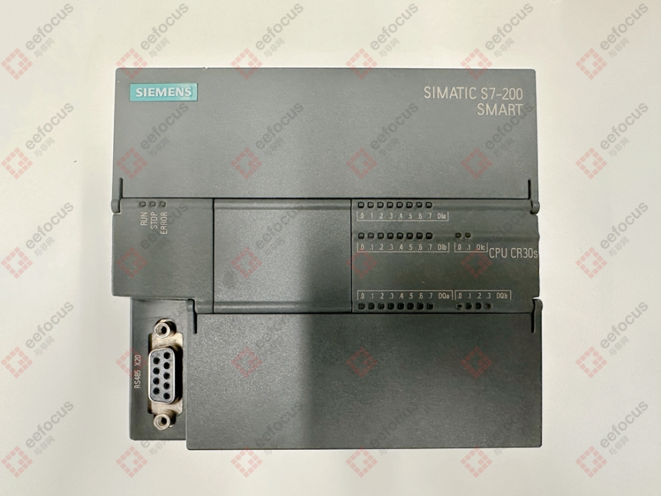
Before disassembly, this S7-200 SMART PLC was still in service, with QC marks on both sides, indicating it had not been disassembled before. Observing the overall exterior, it features a screwless design, allowing for easy disassembly.
Disassembly
True to its long service life, the PLC was covered in dust upon disassembly. After cleaning, we can see that the entire PLC structure consists of a standard main control board, I/O interface board, and power supply board, with a stacked architecture achieved through connectors connecting the three PCB boards.
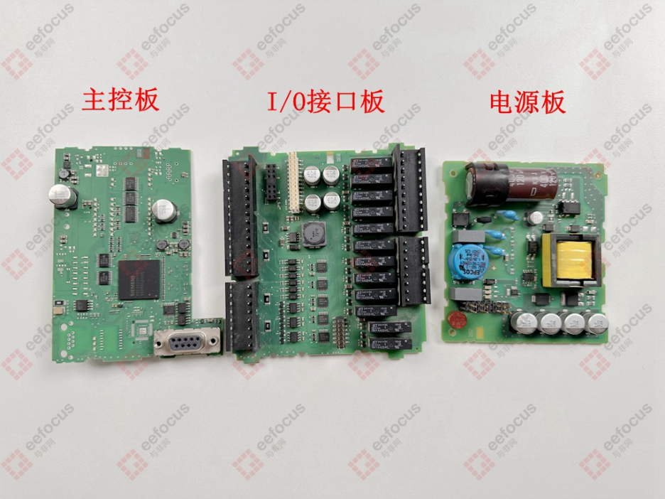
The main control board serves as the “brain” of the PLC, primarily responsible for executing user programs, processing data, managing communications, and coordinating other modules. The I/O interface board safely and reliably collects external field switch signals (buttons, limit switches, relay contacts) or analog signals (such as sensor signals) and drives the output results of the PLC control logic to field actuators (like relays, contactors, indicator lights), while providing electrical isolation to protect the internal circuits of the PLC. The power supply board’s function is straightforward; it safely, reliably, and efficiently converts external AC power into various levels of DC voltage required by the PLC’s internal modules (main control board, I/O board), such as +5V, +3.3V, +24V, etc., and includes overcurrent, overvoltage, and short-circuit protection features.
Having understood the main functions of these PCB boards, let’s take a look at the component selection on each board.
Main Control Board
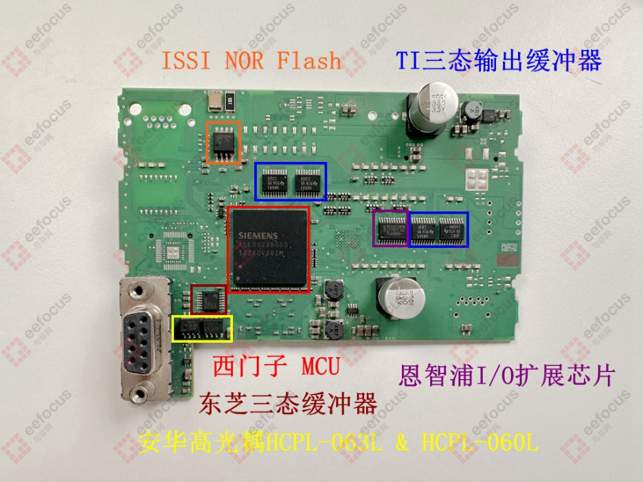
The core controller of the PLC is a product from Siemens itself, but it may also be a custom product from a manufacturer, marked as A5E30235063, which resembles a chip code. Based on the information, it is speculated to be a real-time control MCU product based on the Arm Cortex-R4. The R series is a processor designed by Arm specifically for real-time performance, high reliability, and safety, commonly used in automotive and industrial control applications. One of its main features is low latency, ensuring that control systems can operate stably, reliably, and safely even in harsh environments, responding promptly to external events (I/O changes, communication interruptions, etc.).
Next to the MCU are four Texas Instruments SN74AHC541 buffers, which are 8-channel, 2V to 5.5V buffers with tri-state outputs. They are primarily used to enhance the driving capability of the MCU pins while also providing some degree of logical isolation. This series of products is TTL level compatible, fast, and has strong driving capability, with tri-state output being key, allowing multiple devices to share a bus (data bus, address bus, control signals). The use of multiple devices indicates that the main control board needs to drive many signal lines.
The NXP I/O interface chip PCA9539 is a low-power 16-bit I2C bus and SMBus I/O expansion chip with interrupt and reset functions. Its function is to expand the general I/O capabilities of the MCU, used for monitoring the status of the main board (power status, temperature, fan, etc.), controlling LED indicators, reading configuration jumpers, and providing interrupt and reset functions for easier management.
The ISSI SPI NOR Flash, model IS25LP064, has a capacity of 8MB. It is typically used to store boot programs, operating system kernels, firmware programs, and other essential code for startup and operation.
Next to the DB9 interface is a Toshiba logic device, a tri-state buffer, model 74VHC125FT, which serves a similar function to the Texas Instruments buffer mentioned above, used for buffering and isolating specific signal lines that need control.
Two optocouplers from Avago are used for electrical signal isolation, with models HCPL-060L and HCPL-063L.
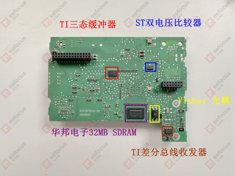
The chips on the back of the main control board are as follows:
Texas Instruments tri-state buffer SN74AHC541PWR, which is the same model as the four on the front, serving the same function.
STMicroelectronics low-power dual voltage comparator LM2903. It may be used for voltage/threshold detection, such as monitoring whether the power supply voltage is within the normal range (under-voltage/over-voltage protection), monitoring whether the output of temperature sensors exceeds limits, or other scenarios requiring analog comparison.
Winbond 32MB SDRAM,model W948D2FBJX6E.
Vishay low input current optocoupler, model V0617A.
Texas Instruments differential bus transceiver SN75176A, which corresponds to the RS485 communication circuit of the DB9 interface on the front, a common point-to-point or network communication method for PLCs.
I/O Interface Board
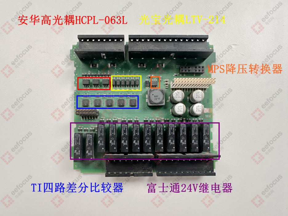
After reviewing the chip selection on the main control board, let’s look at some components on the interface board. From the layout, the top is for inputs, and the bottom is for outputs. From the row of components at the bottom, we can roughly determine that they are relay outputs, so let’s see which chips are used.
Three Avago HCPL-063L optocouplers, high-speed optocouplers suitable for digital signals; six Lite-On LTV-214 optocouplers, commonly used standard optocouplers, likely at a lower cost.
MPS DC/DC buck converter MP2467DN provides a stable local power supply for the logic circuits on the I/O board (optocoupler input/output side, comparators, status indicators, etc.).
Five Texas Instruments quad differential comparators LM2901, a very classic chip. Its functions are quite diverse, such as input level conversion/shaping: comparing analog inputs with preset thresholds and outputting clean digital level signals to the MCU. It can also be used for overcurrent/undervoltage detection, monitoring whether the input or output channels’ current/voltage is abnormal (for protection). Additionally, it can be used for pulse width detection/frequency detection, etc.
The output side features a row of Fujitsu 24V relays, model MYAA024E, providing high isolation output channels. For example, the low-voltage circuit inside the PLC drives the relay, which controls the on/off of the external high-voltage circuit. It can also be used to drive indicator lights, small contactor coils, alarms, etc.
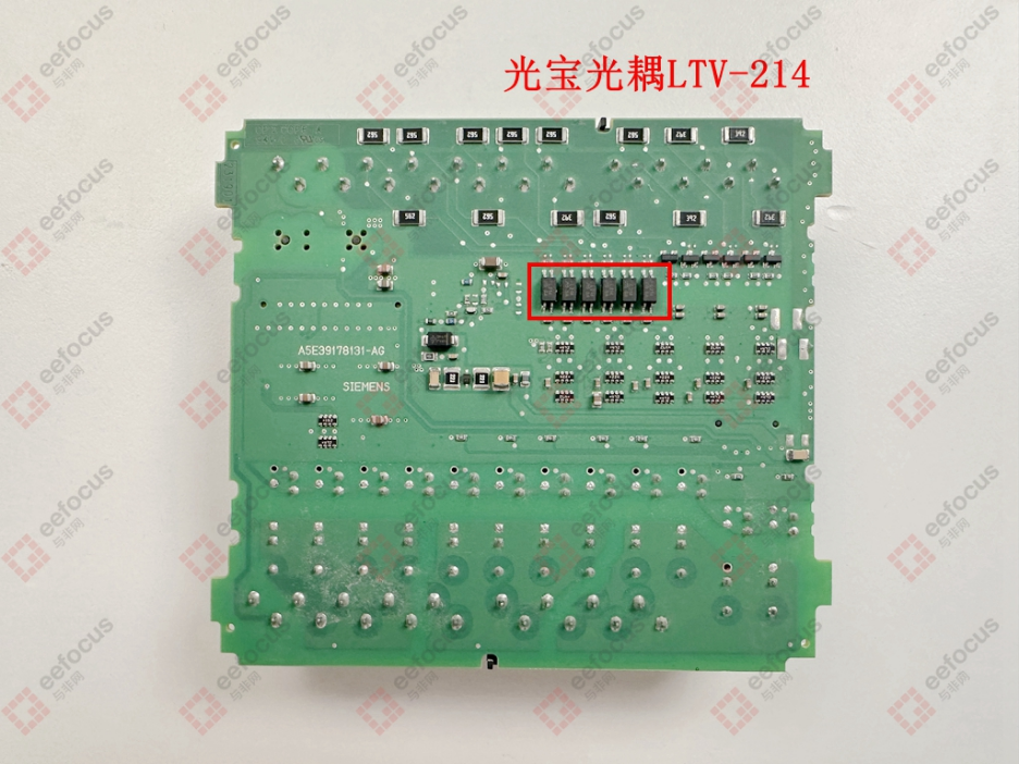
The back of the I/O interface board mainly consists of six Lite-On LTV-214 optocouplers.
Power Supply Board
Finally, let’s take a look at the power supply board. Due to the numerous components, the layout may not appear very aesthetic, but Siemens’ PLC power supply board layout is quite pleasing. The entire circuit layout is clear, both in terms of component arrangement and PCB wiring, so let’s examine the components on it.
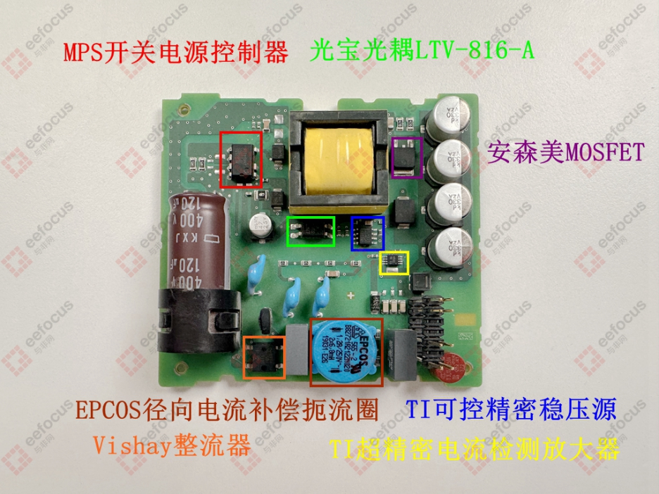
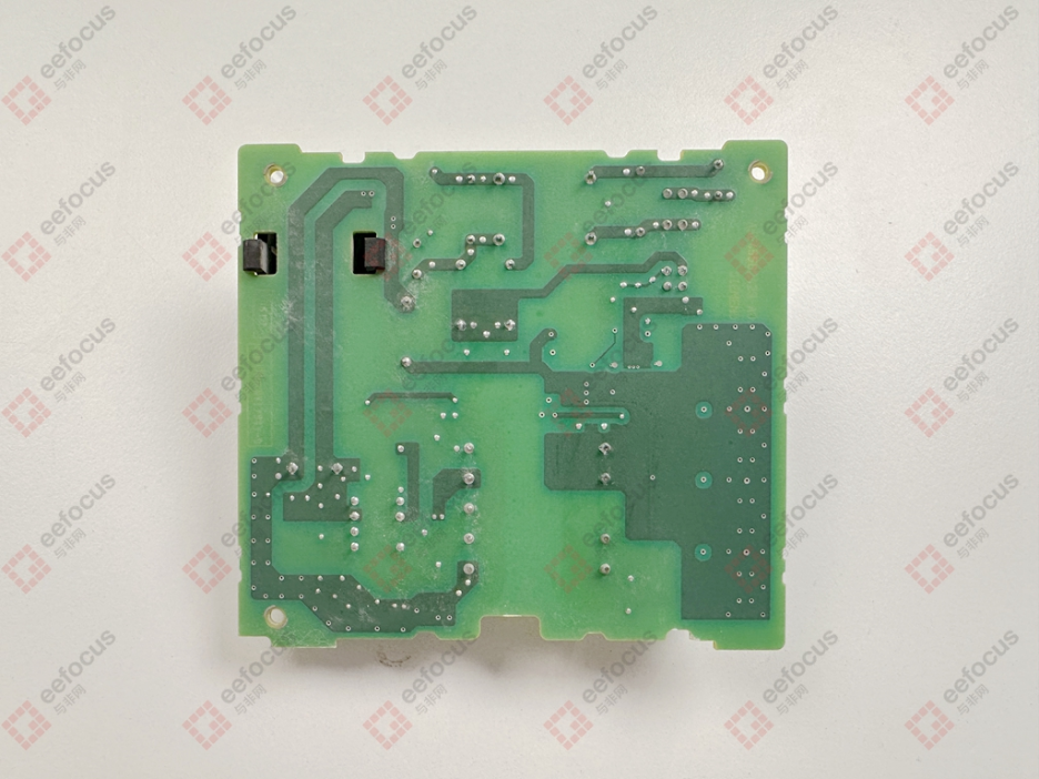
The input side (primary side) includes fuses, thermistors, safety capacitors, Y capacitors, radial current compensation chokes, rectifiers, a large aluminum electrolytic capacitor for filtering after rectification, MOSFETs, PWM controllers, etc.
Among them, the choke, which is a common mode inductor, is a product from EPCOS, and this component costs around ten RMB, more expensive than entry-level MCUs. Its function is to form part of the input EMI filtering circuit, working with capacitors to filter out interference from the power grid and prevent high-frequency interference generated by the switching power supply from returning to the grid, enhancing the power supply’s anti-interference capability and meeting electromagnetic compatibility standards. The rectifier is Vishay’s DF1510S.
The MOSFET is from ON Semiconductor, and the PWM controller is ON Semiconductor’s HF01B00 quasi-resonant controller, forming the core of the switching power supply, generating high-frequency PWM waves to control the power switching device.
There is an optocoupler from Lite-On providing feedback isolation for the output voltage at the junction between the primary and secondary circuits, model LTV-816-A.
On the output side circuit, there is a Texas Instruments controllable precision voltage reference TL431, serving as the voltage reference and error amplifier for the output side.
These chips can be connected together; the Lite-On optocoupler transmits the sampled output voltage signal from the secondary side (processed by the Texas Instruments reference source TL431) back to the primary side controller (MPS HF01B00<MPS1833>), achieving closed-loop voltage regulation control while isolating the high-voltage input side from the low-voltage output side.
Additionally, the switching power supply circuit also uses Texas Instruments’ ultra-precision current sensing amplifier INA190-Q1, which detects the voltage drop across a small resistor in the output loop and amplifies it into a proportional voltage signal (such as sent to TL431 or MCU) for overcurrent protection, power status monitoring (fault diagnosis), or current control.
The final output uses STMicroelectronics’ Schottky diode as the rectifier and four solid-state filter capacitors for filtering.
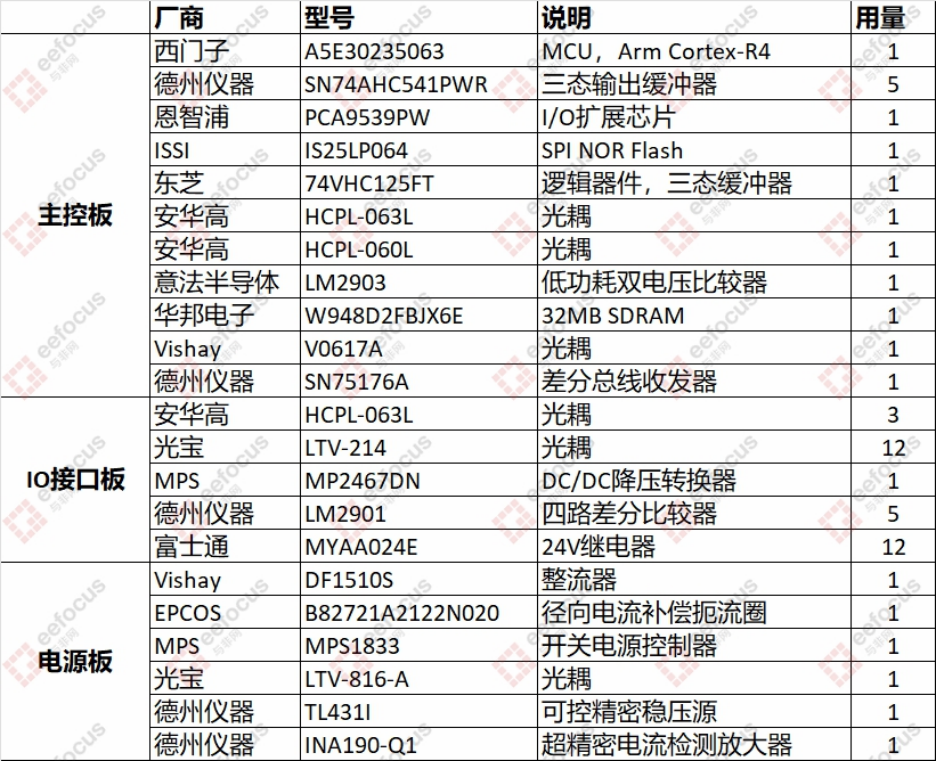
The main BOM is shown in the table below, where MPS1833 is the HF01B00 quasi-resonant PWM controller.
Click to play
Summary
Through the disassembly of the Siemens S7-200 SMART PLC, we ultimately observed the internal structure layout and component selection. The results show that the hardware design follows modular and isolation design principles, with three separate PCB boards connected via connectors. Optocouplers are the absolute mainstay for isolation in the PLC, widely used in I/O interfaces, communication interfaces, power feedback, etc., ensuring the safety of internal circuits. The core MCU is selected for industrial and high-reliability applications, based on the ARM Cortex-R4, and the components involved are generally industrial or automotive grade. Logic devices, comparators, and others are all mature and reliable general-purpose models. Overall, it is truly a classic compact PLC.
A group of like-minded friends gathers in the Knowledge Circle Sphere
Join the “Abao Talks Cars” Knowledge Circle to gain access to related learning materials for these modules (currently including research reports, online expert sharing, and offline closed-door meetings), covering 16 major sections, detailed list as follows: