Follow “Coder Loves Learning“, set the “Star Official Account“
Exclusive Content Delivered First!
The STM32MP157 features an A7 core and an M4 core. Previous articles introduced some topics based on the A7 core. This article will cover the development of the M4 core and the use of STM32CubeIDE software during development.
1 Creating an LED Project in STM32CubeIDE
STM32CubeIDE is an integrated multi-OS development tool and is part of the STM32Cube software ecosystem.
Download link: https://www.st.com/zh/development-tools/stm32cubeide.html#st-get-software
First, install STM32CubeIDE using the standard exe installation; this will not be elaborated here.
1.1 Creating a New Project
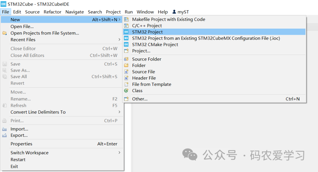
File, New, STM32 Project
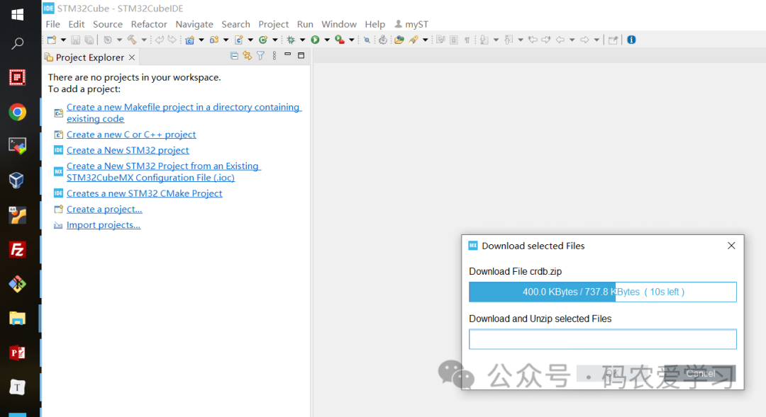
The first time, some files will be downloaded.
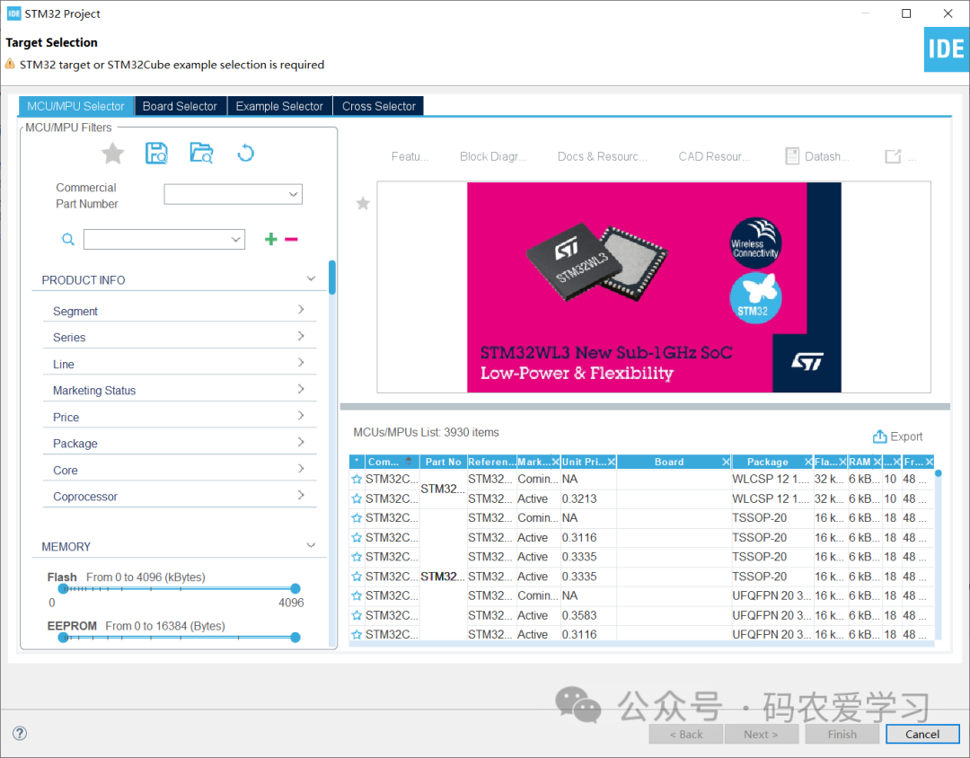
After the download is complete, the interface will show four tab-switching windows:
- MCU/MPU Selector: MCU/MPU chip selection window
- Board Selector: Selection window for some official ST development boards
- Example Selector: Example program selection window for existing examples on ST official development boards
- Cross Selector: Cross-reference tool window to select the corresponding CPU model, which will pop up a resource comparison interface for the same system CPU model
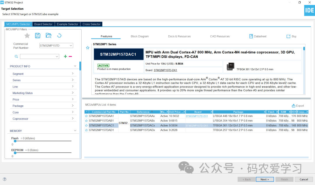
After entering STM32MP157D in the search box, you can see four specific models on the right. The STM32MP157DAC1 describes the STM32MP157D-DK1 development board, so select this one:
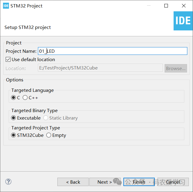
After clicking Next, set the project name, for example, 01_LED, and you can check Use default location to specify the location:
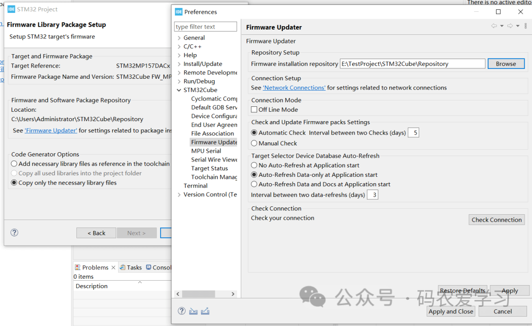
After clicking Next, you can modify the firmware package location by clicking Firmware Updater:
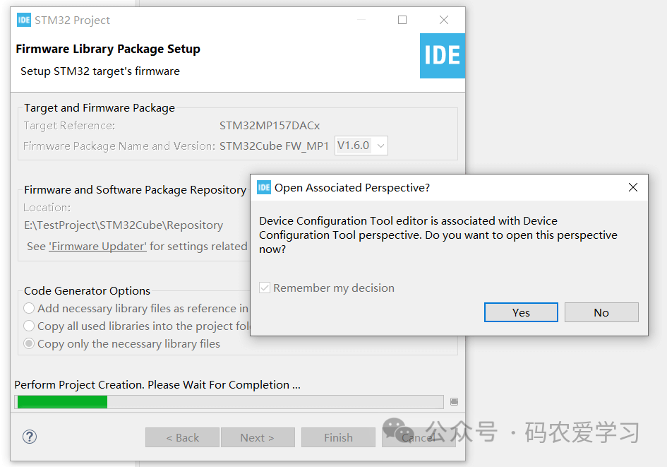
After clicking Finish, a window will pop up asking to Open Associated Perspective; just click Yes:
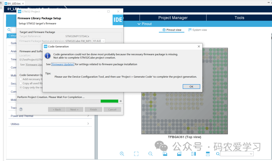
Downloading certain files requires logging into an ST account. If you haven’t logged in, you may see a failure popup like the one below; you can ignore it for now and handle it later.
Then you will arrive at this interface, which also has four switchable window tabs:
- Pinout & Configuration: Pin configuration window
- Clock & Configuration: Clock configuration window
- Project Manager: Project management configuration window
- Tool: Related tools configuration window
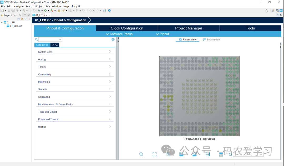
As mentioned earlier, due to not logging into the ST account, some files failed to download. Now you can try downloading again by clicking on Manage embedded software packages in the Help menu, which will pop up the following window. Find STM32MP1, check the Package, and click Install:
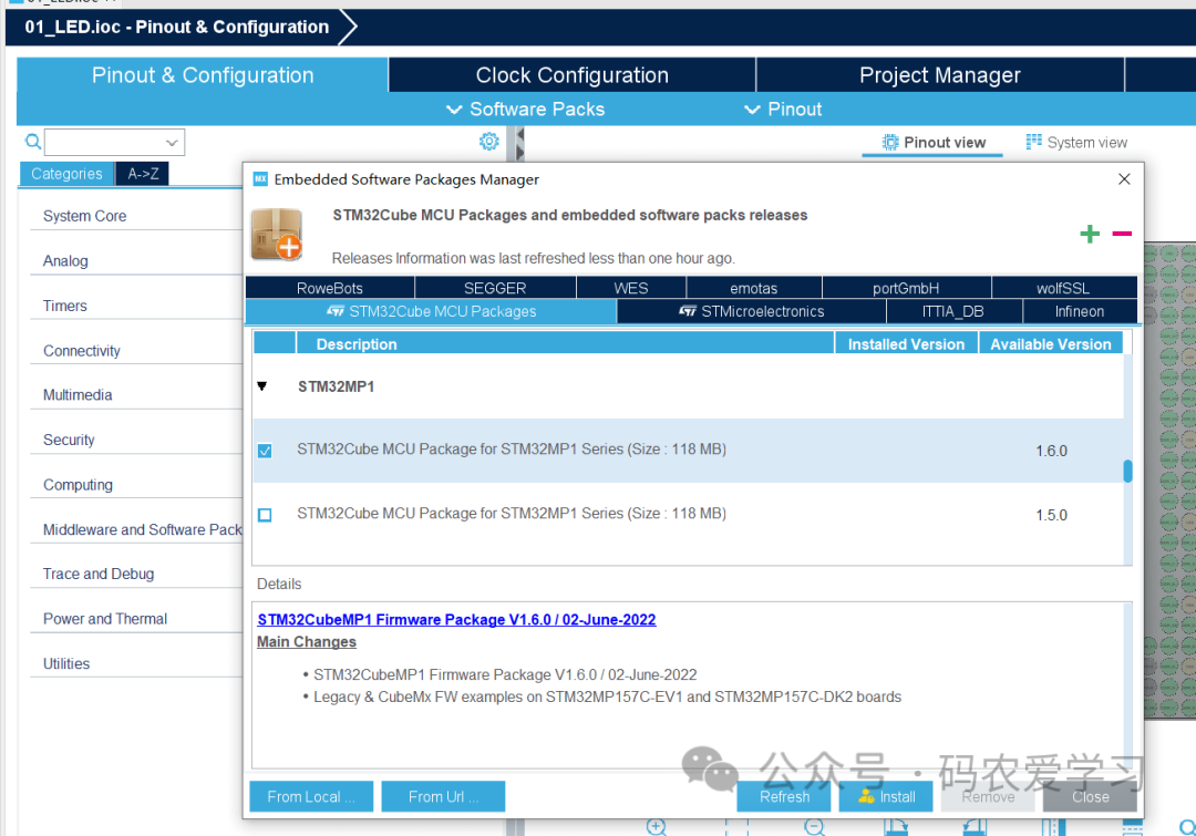
Then it will download again:
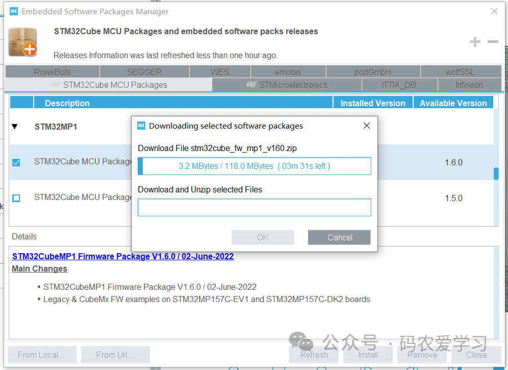
Once the download is complete and successfully associated, it will turn into a green square:
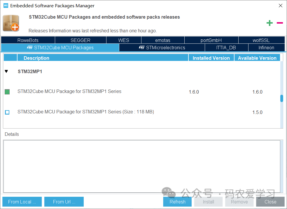
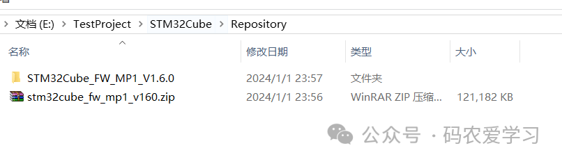
You can check the downloaded files in the download location:
1.2 Configuring Pins
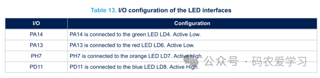
Use LED LD7 for LED control; according to the documentation, it corresponds to pin PH7, which lights up with a high level:
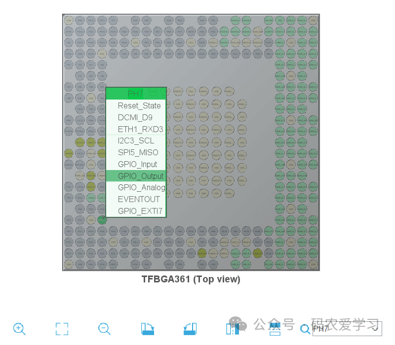
Search for pin PH7 and set it to Output mode:
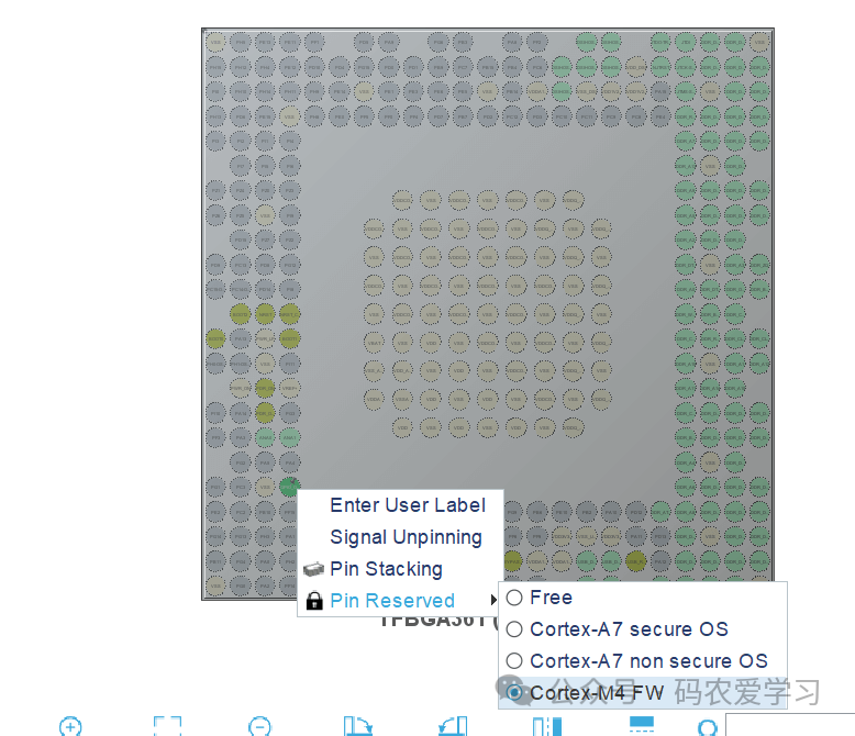
Then right-click, set Pin Reserved, and select Cortex-M4 FW.
Click on System Core on the left, then GPIO, where you can configure GPIO settings such as pull-up/pull-down, speed, etc.:
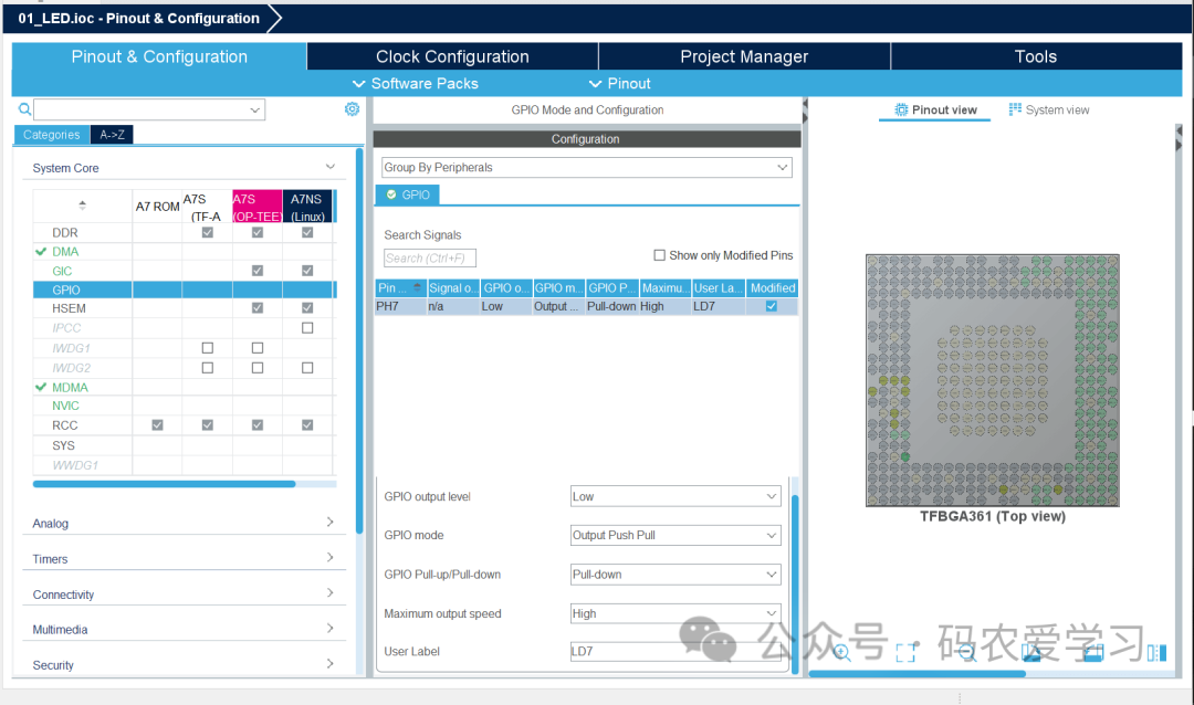
Then, the clock does not need further configuration. In the project management section, make sure to check the following two items:
- Copy only the necessary library files, the project will copy the required HAL library files from the STM32Cube MCU software package, and unused files will not be copied.
- Generate peripheral initialization as a pair of ‘.c/.h’ files per peripheral, which means each peripheral will generate independent ‘.c/.h’ files. If this option is not checked, the initialization code related to peripherals will be generated in main.c instead.
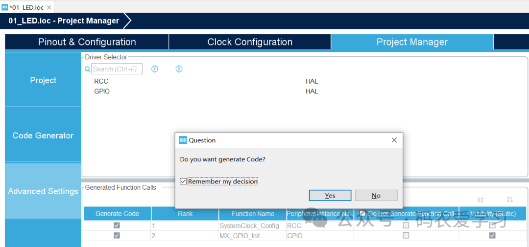
Finally, press Ctrl+S to save, and it will prompt you to generate code; click Yes:
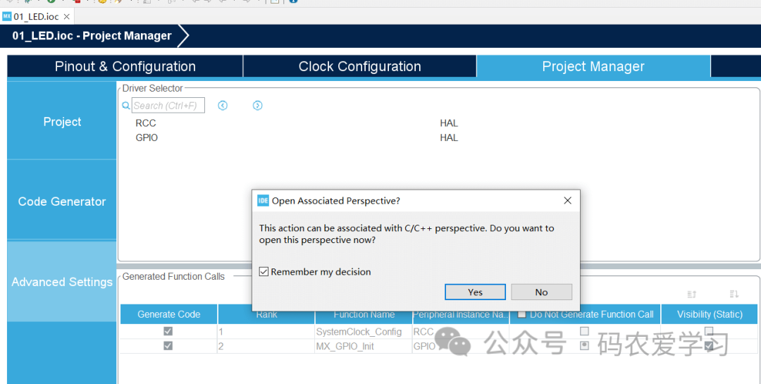
Then there will be another popup; just click Yes:
1.3 Modifying Code and Compiling
Add the logic code to control the LED on and off in main.cpp:
HAL_GPIO_WritePin(LD7_GPIO_Port,LD7_Pin,GPIO_PIN_SET);
HAL_Delay(500);
HAL_GPIO_WritePin(LD7_GPIO_Port,LD7_Pin,GPIO_PIN_RESET);
HAL_Delay(500);
Note the position of code addition; it should be added between the paired BEGIN and END regions:
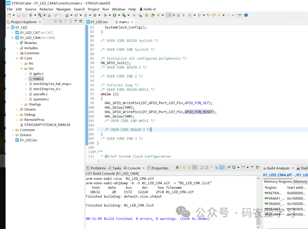
Then click the “hammer” icon to compile, and you should see 0 errors and 0 warnings as shown in the above image.
2 Programming and Testing
2.1 Switching the BOOT Mode
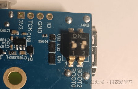
Set the development board’s BOOT configuration BOOT0 to OFF and BOOT1 to ON, and connect the ST-LINK interface of the board to the computer.
2.2 Configuring ST-Link
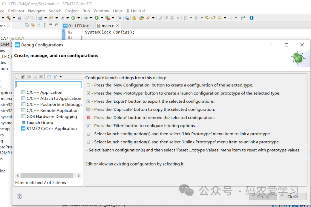
In the menu, select Debug Configurations under Run…
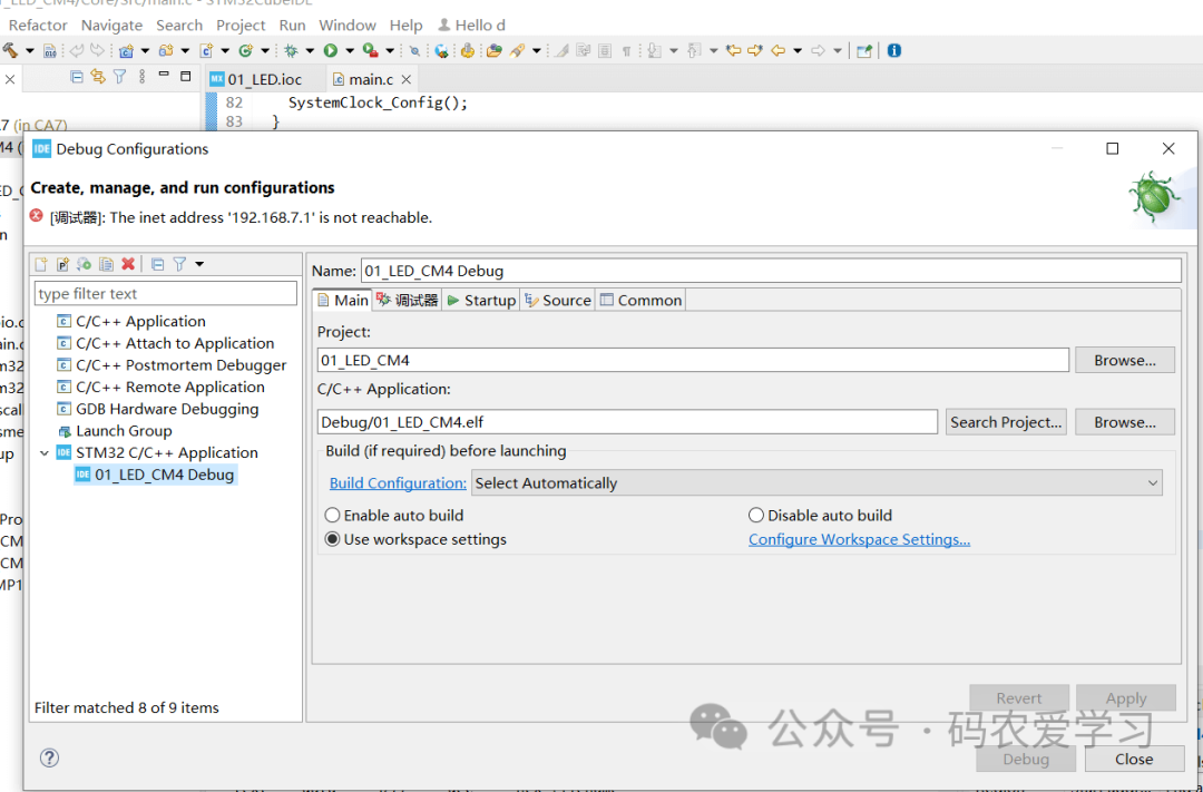
Then, double-click STM32 Cortex-M C/C++ Application to automatically create and open a configuration item named HAL_LED_CM4 Debug:
Switch to the debugger window and select thru JTAG/SWD link:
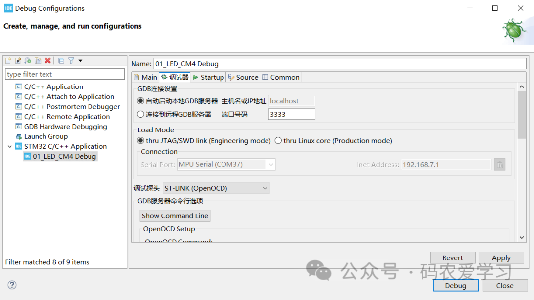
Then click Apply, and Debug to start debugging.
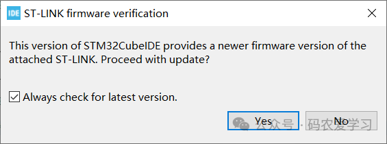
The first time you download a program using ST-Link in STM32CubeIDE, the system will prompt you to update the ST-LINK firmware:
In the pop-up window, select ST-LINK:
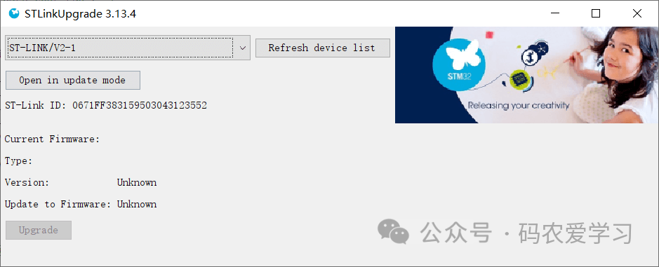
Then unplug and re-plug the USB cable, click Open in update mode, and a new interface will pop up:
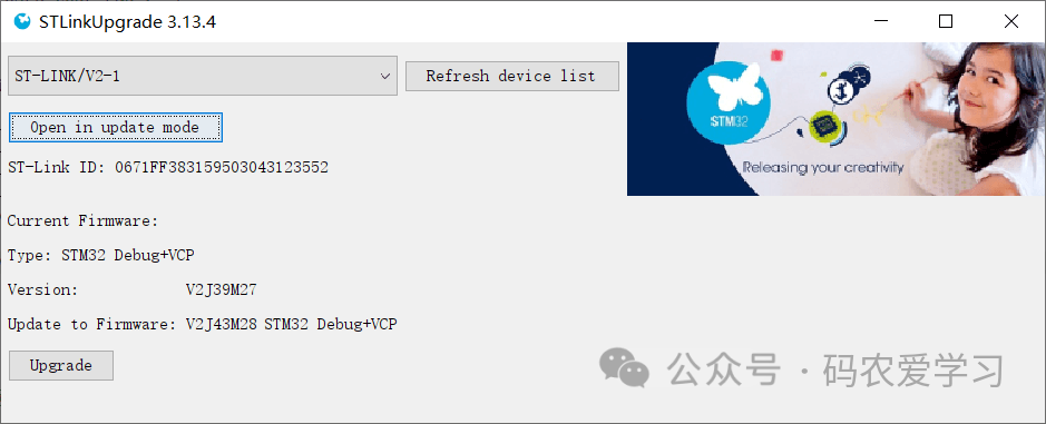
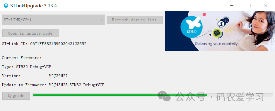
Click Upgrade to update the ST-Link firmware, and wait for the update to complete.
2.3 Debugging the Running Program
Then continue in the previous debugger window, click Debug to start debugging.
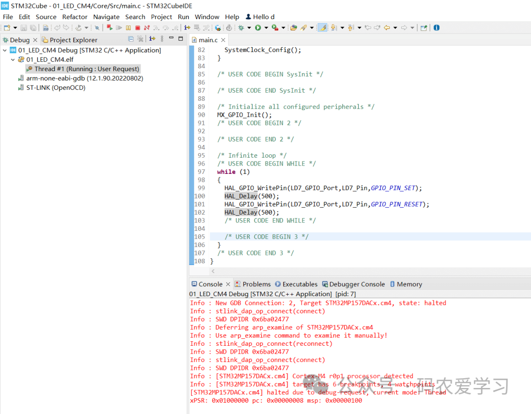
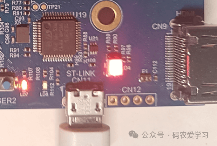
After running at full speed, you will see the orange LED LD7 blinking:
2.4 Running ELF Firmware via Linux System
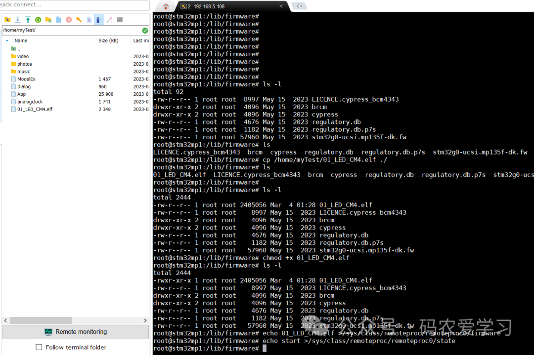
Switch the board’s BOOT switch to boot Linux from the SD card, then copy the ELF file compiled by STM32CubeIDE:
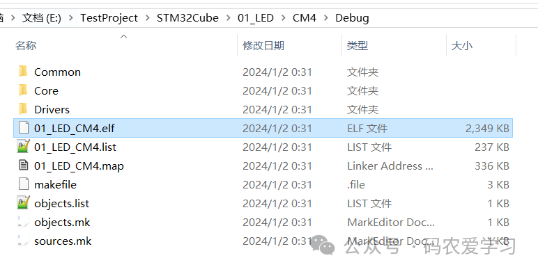
For example, 01_LED_CM4.elf, to the /lib/firmware directory of the development board, add executable permissions, and then run the M4 core program using the following commands:
# Load firmware
echo 01_LED_CM4.elf >/sys/class/remoteproc/remoteproc0/firmware
# Start firmware
echo start >/sys/class/remoteproc/remoteproc0/state
3 Summary
This article introduced the development process of the M core program for the STM32MP157D-DK1 development board, including creating a project in STM32CubeIDE, configuring pins, and writing programs, ultimately achieving a basic LED blinking experiment.
Related Articles
STM32MP157D-DK1 Firmware Programming STM32MP157D-DK1 Qt Image Building STM32MP157D-DK1 Qt Program Cross-compilation and Running Tests TRIZ Innovation Theory (26~30) TRIZ Innovation Theory (31~35)
Read the original article, discover more exciting content~