
Source | International Journal of Heat and Mass Transfer
Link | https://doi.org/10.1016/j.energy.2025.139269
01
Background Introduction
As we enter the 5G era, terminal devices continue to evolve towards being lighter and more high-performance. Meanwhile, new electronic products such as foldable terminals and flexible wearable devices are emerging, with increasingly compact internal structures, significantly increasing the difficulty of thermal management. Traditional metal vapor chambers, while possessing excellent thermal conductivity, struggle to meet the dynamic deformation requirements of bending and folding, whereas polymer-based flexible vapor chambers face inherent issues such as the high-temperature release of non-condensable gases and insufficient long-term reliability. In this context, achieving a balance between “ultra-thin” and “flexible” while ensuring efficient heat dissipation has become a core challenge in current thermal management technology. Notably, the rise of high-precision 3D printing technology has opened up a new technical path for developing structurally flexible and performance-stable ultra-thin flexible vapor chambers.
02
Highlights of the Results
Recently, the team led by Professor Xue Yahui at Southern University of Science and Technology innovatively adopted the “high-precision stereolithography 3D printing + gas-liquid co-planar wicking core structure” technology path to successfully develop ultra-thin flexible vapor chambers with thicknesses of only 0.25 mm (copper-based) and 0.34 mm (graphene-based). The core breakthroughs are reflected in three aspects: 1) Material-Process Dimension: It overcomes the limitations of traditional polymer-based flexible vapor chambers that easily produce non-condensable gases, as well as the challenges faced by metal-based vapor chambers in balancing ultra-thin and high-precision forming processes, achieving direct printing and metallization of the wicking core structure on soft copper and high-conductivity graphene films, significantly enhancing the thermal reliability and structural integrity of the devices; 2) Structure-Mechanism Dimension: Through a combination of experiments and thermal resistance analysis, the coupling mechanism of filling ratio and bending angle on the thermal transport performance of ultra-thin vapor chambers is systematically revealed, establishing a 60% filling ratio as the optimal condition, providing key design basis for the performance optimization of flexible vapor chambers; 3) Performance-Application Dimension: The developed graphene-based ultra-thin flexible vapor chamber, with a thickness of only 0.34 mm, maintains an equivalent thermal conductivity of up to 5800 W/(m·K) and an extremely low thermal resistance of 1.2 K/W after 100 bending cycles, providing a reliable heat dissipation solution for high-performance flexible electronics. The research results titled “High-precision additive manufacturing enabled ultra-thin flexible vapor chamber for adaptive and efficient electronic cooling” were published in the International Journal of Heat and Mass Transfer.
The author of this research, Associate Professor Xue Yahui from Southern University of Science and Technology, will attend the 6th Thermal Management Industry Conference and Expo as a speaker to share a conference report titled “High-performance Liquid Cooling Technology Based on Additive Manufacturing”.

Based on additive manufacturing technology, the laboratory has developed high-performance ultra-thin stainless steel vapor chambers and ultra-thin flexible vapor chambers, integrated ceramic microchannel coolers, and silicon-based microchannel coolers, all of which significantly enhance heat dissipation capabilities compared to traditional technologies.

📅 Conference Date: December 3–5, 2025📍 Conference Location: Shenzhen International Convention and Exhibition Center, Baoan (Hall 10)
03
Illustrated Guide
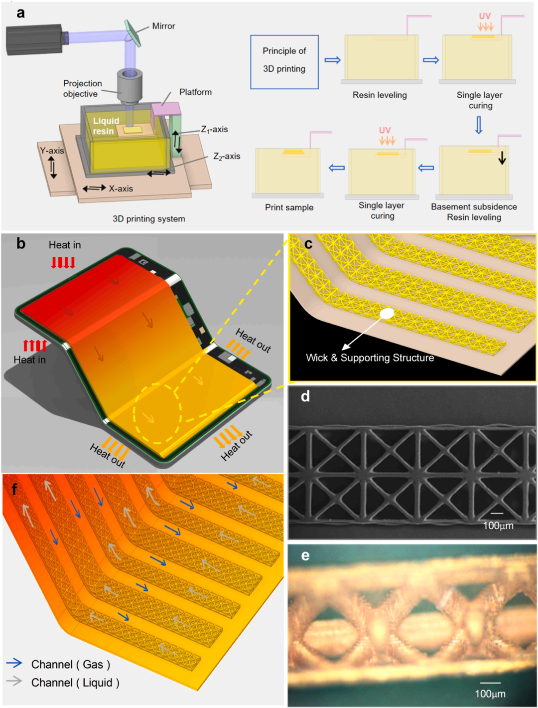 Figure 1. Schematic diagram and experimental manufacturing of UTFVC. (a) Schematic diagram of the high-resolution stereolithography 3D printing process. (b) Potential applications in foldable mobile devices. (c) Gas-liquid co-planar core structure with body-centered orthorhombic (BCO) array structure. (d) SEM image of the core structure. (e) Optical view of the cross-section of the core structure after copper plating. (f) Schematic diagram of the flow path of the working fluid in the UTFVC cavity.
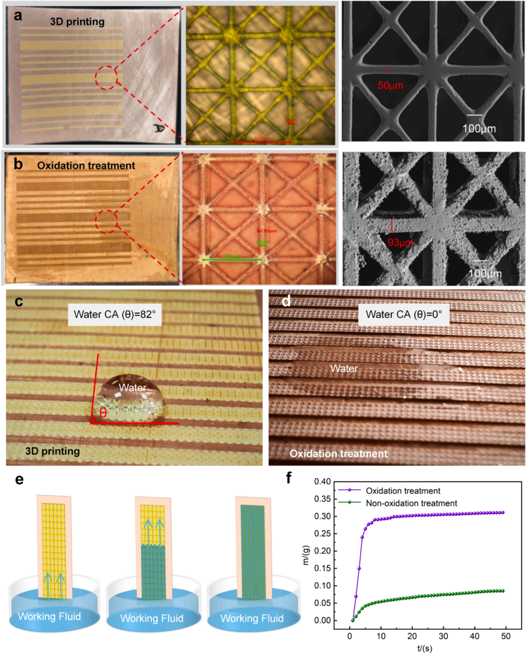 Figure 2. Copper plating and capillary core absorption testing of lattice core structure. (a) Printed 3D structure. (b) Copper-plated lattice structure after oxidation treatment. (c) Water contact angle (θ = 82 °) on the surface of the intrinsic 3D printed resin. (d) Instant droplet spreading after oxidation treatment (θ = 0 °). (e) Schematic diagram of the capillary core absorption process. (f) Capillary absorption mass (m) as a function of time (t).
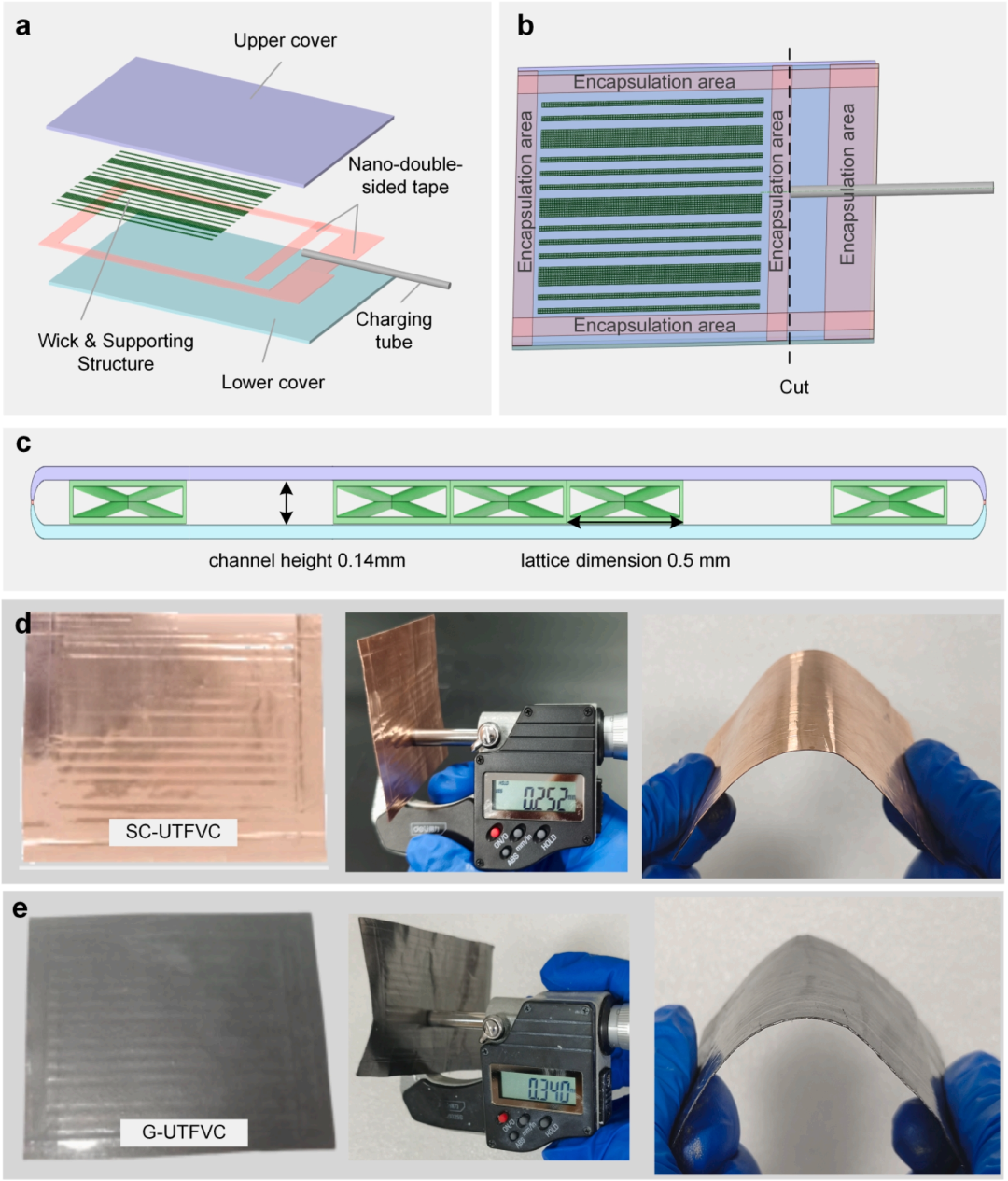 Figure 3. Assembly of UTFVC: (a) Exploded view of the layered structure of UTFVC. (b) Schematic assembly of components bonded with nano double-sided tape. (c) Schematic cross-section of the gas-liquid co-planar structure of UTFVC. (d) Freely deformable SC-UTFVC with a thickness of 0.25 mm. (e) Freely deformable G-UTFVC with a thickness of 0.34 mm.
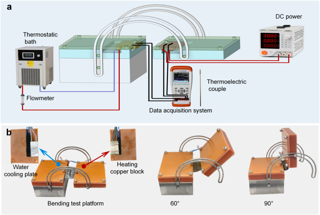 Figure 4. Experimental setup for thermal performance testing: (a) Schematic diagram of the transverse thermal resistance testing platform. (b) Bending testing platform for measuring thermal resistance at different bending angles.
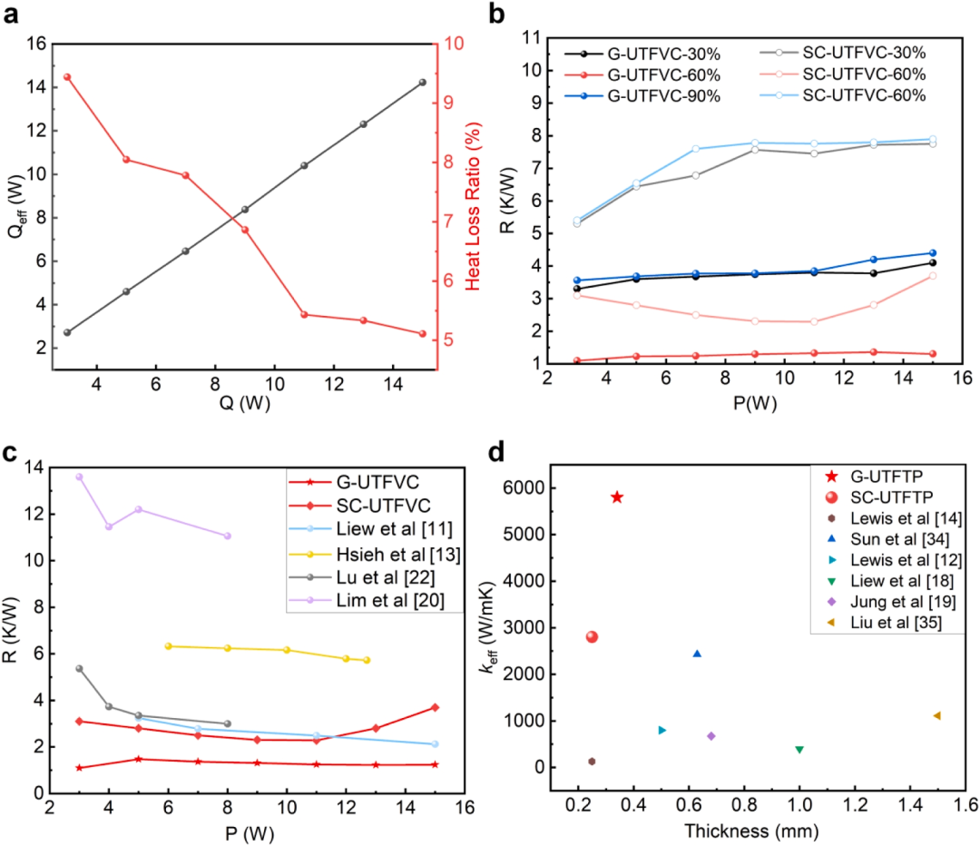 Figure 5. Thermal resistance characterization of UTFVC. (a) Thermal losses from testing. (b) Thermal resistance at different heating powers (3-15 W) with 30%, 60%, and 90% working fluid filling ratios. (c) Comparison of thermal resistance of two UTFVC configurations with literature values. (d) Effective thermal conductivity (keff) compared with literature results of two UTFVCs.
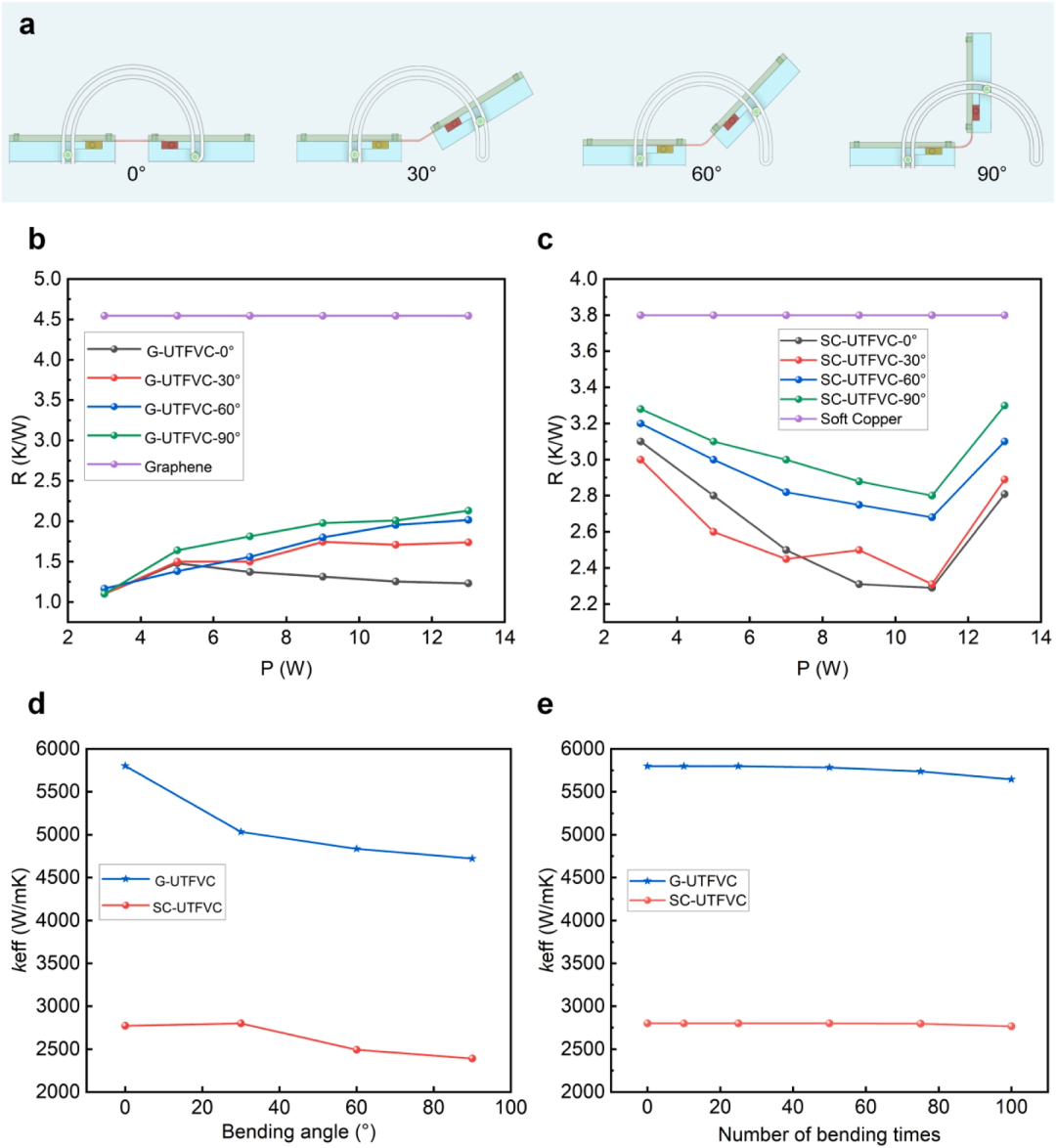 Figure 6. Thermal performance of UTFVC under bending conditions. (a) Schematic diagram of the testing platform showing bending angles of 0 °, 30 °, and 60 °. (b) Variation of thermal resistance of G-UTFVC with bending angle at different heating powers. (c) Variation of thermal resistance of SC-UTFVC with bending angle under different heating power conditions. (d) Comparison of effective thermal conductivity (keff) between SC-UTFVC and 90 °C. (e) Changes in keff of G-UTFVC and SC-UTFVC after cyclic bending.
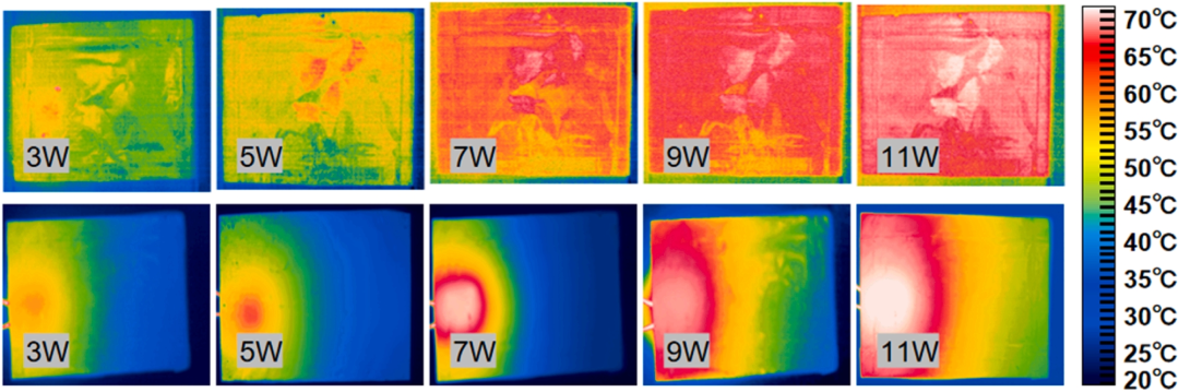 Figure 7. Temperature distribution of G-UTFVC (top) and pure graphene film (bottom) at heating powers from 3 W to 11 W.
 ——Recommended Reading——







 ★ Platform Statement
Some materials are sourced from the internet, and copyright belongs to the original authors. The purpose of sharing is solely for industry information dissemination and communication, and does not represent the position of this public account or verify its authenticity. If there are any issues, please contact us for timely handling. Contributions and sharing are welcome!
★ Contact Information
Phone:15356097253 (WeChat same number)