Abstract
With the rapid development of electronic products, the application fields of electronic devices are constantly expanding. From the past, where electromechanical products were limited to general industrial applications, to today, where electronic equipment is widely used in aerospace, navigation, military, and other fields. The broad application of electronic equipment means that higher requirements are placed on electronic equipment: high reliability, high quality, and the ability to adapt to various harsh working environments, which has led to the emergence and rapid development of three-proof protection technology (moisture-proof, mildew-proof, and salt spray resistance).
The three-proof coating of printed board assemblies in electronic equipment is an important component of three-proof technology, and its protective performance directly affects the reliability of electronic equipment. To improve the corrosion resistance of electronic equipment, reduce equipment failure rates, enhance the reliability of electronic devices, and extend service life, it is essential to protect and coat the printed board assemblies that make up electronic devices.。
1. Coating Materials
(1) Requirements for Coating Materials
The protective coating materials for printed board assemblies belong to special coatings and should meet the following requirements: (1) Good electrical performance, with minimal changes in electrical performance with temperature and humidity variations; (2) Good moisture resistance, with the ability to quickly restore original performance under normal conditions after moisture exposure; (3) Resistance to mildew and salt spray; (4) Good adhesion to substrates and components, with the ability to withstand repeated temperature shocks from -60℃ to +125℃ and tests in humid, mildew, and salt spray environments; (5) The coating should be polymer-based to reduce the possibility of pinholes left by solvent evaporation; (6) The coating should not cause discoloration, wrinkling, or corrosion of PCB, metal plating, solder, or component surfaces; (7) Good processability, suitable for dipping, spraying, and brushing processes, with fast surface drying speed.
(2) Commonly Used Coating Materials
Commonly used coating materials mainly include four types: acrylic (AR), polyurethane (UR), epoxy resin (ER), and silicone (SR).
(3) Performance of Commonly Used Coating Materials
The performance of commonly used coating materials is shown in Table 1.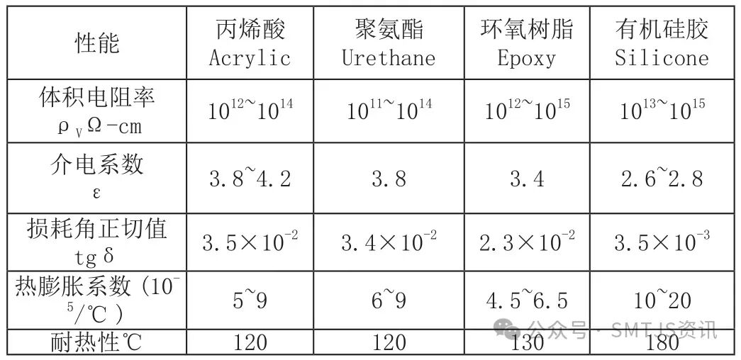
Table 1 Comparison of Coating Material Performance
(4) Principles for Selecting Coating Materials
The physicochemical properties and process performance of coating materials vary, and suitable coating materials should be carefully selected based on specific usage requirements and available process conditions.
1. Acrylic
Easy to apply, with ideal electrical performance, physical properties, and mildew resistance, long service life, short curing time, and no exothermic reaction during curing, preventing damage to heat-sensitive components, and no shrinkage after curing. However, this type of coating is sensitive to solvents, making it easy to repair. Suitable for PCB coating in Class A environments.
2. Polyurethane
Available in single-component and dual-component types, with good long-term dielectric properties, excellent moisture resistance, and chemical resistance. Special stripping agents must be used for replacing components or repairing circuit boards. The circuit board must be kept clean before coating, especially ensuring no moisture is present.
3. Epoxy Resin
Generally a dual-component type, with a short service life, good moisture resistance, salt spray resistance, and chemical resistance. Physical means must be used to strip the epoxy resin film for replacing components or repairing circuit boards, and protective measures should be taken for fragile components before coating.
4. Silicone
Excellent electrical performance, with lower loss and dielectric constant values than other types of coatings, particularly good thermal performance, capable of continuous operation at 200℃, and also very good moisture and corrosion resistance. Suitable for coating high-frequency and microwave boards; also suitable for circuit boards operating at high temperatures.
Based on the above principles for selecting coating materials and combined with our actual situation, after extensive research, we ultimately chose silicone-based three-proof paint.
2. Overview of Three-Proof Coating Methods and Processes for Printed Circuits
(1) Traditional Coating Methods and Processes
Traditional protective coating methods for printed circuit boards mainly include dipping, brushing (flow coating), and manual spraying.
1. Dipping
The dipping process can achieve good coating results, but due to the exposure of the coating to air, it requires high viscosity of the coating, and components such as adjustable capacitors, trimmer cores, potentiometers, and unsealed devices like crystal oscillators cannot be coated using the dipping method. Additionally, dipping is greatly affected by factors such as the temperature of the dipping container, dipping time, withdrawal speed, and drainage time.
2. Brushing (Flow Coating)
Low investment and wide applicability, mainly used for coating small volume products or for repairing coatings, but its conversion efficiency is low, requiring high skill from operators. Clear markings are needed for areas that should not be coated; otherwise, errors are likely, and product consistency is poor.
3. Manual Spraying
Manual spraying is the most commonly used process, suitable for products with less dense component arrangements that require minimal localized protection and are not overly demanding. Similarly, strict protection is needed for components and areas that should not be coated to prevent contamination, and specialized fixtures or protective films should be used for printed plugs and grounding areas.
In summary, the above three traditional coating processes have the following disadvantages:
(1) Cannot meet the requirements for coating high-density circuit boards;
(2) Coating thickness is difficult to control, with poor consistency affecting product quality;
(3) Non-coated areas require masking and demasking, with tape residue difficult to remove, complex processes prone to errors, and material waste;
(4) Manual operation has high labor intensity, low efficiency, and is prone to errors;
(5) Serious hazards to the environment and operators.
(2) Automatic Selective Coating Process
With the increase in assembly density of circuit boards, traditional coating methods can no longer meet the requirements of protective coating processes. The automatic selective spraying coating method has become a new type of coating process. Its principle is to change the manual operation of three-proof protective coating of circuit boards to automated operation controlled by a PC, achieving precise positioning for selective spraying without the need for masking protection processes, suitable for certain batch sizes, high assembly density, and requiring high coating precision for circuit board protection.
The advantages include good coating uniformity, controllable coating thickness, good spraying consistency, and protection for operators and the production environment.
3. Key Process Parameters for Selective Coating
The quality factors of coating mainly consist of coating thickness, coating width, coating uniformity, bubbles, spraying edge precision, and spraying pattern regularity. Many complex factors affect these quality factors. Below are several key process parameters for selective coating and their impact on spraying quality.
(1) Pressure
Pressure includes spraying pressure, atomization pressure, and supply pressure.
1. Spraying Pressure
For the spray valve, spraying pressure is mainly used to lift the internal spring of the spray valve and raise the spray valve’s impact needle, thereby opening the fluid outlet of the spray valve. Due to the mechanical structure of the spray valve, the greater the spraying pressure, the larger the outlet, and vice versa.
2. Atomization Pressure
Atomization pressure is applied to the side of the spray valve outlet, causing the fluid to form a fan-shaped mist at the outlet of the spray valve rather than a linear flow, achieving the spraying purpose.
Uneven atomization pressure can lead to non-uniform fan-shaped fluid, resulting in irregular shapes on the circuit board, affecting spraying uniformity. The uniformity of atomization pressure can be visually observed; if the fluid blown out is uneven, check whether the atomization pressure outlet of the spray valve is blocked by solidified coating.
3. Supply Pressure
Supply pressure is the pressure used to output the coating.
(2) Coating Viscosity
Different viscosities of coatings have different flow properties, and the speed of curing in air also varies. Commonly used silicone coatings for circuit boards generally have a viscosity of less than 1Pa/s, with good flow properties and spraying effects. Based on our process experimental experience, coatings with a viscosity below 0.5Pa/s have better spraying effects than those above 0.5Pa/s.
(3) Spraying Height
Coating height is the vertical distance from the spray valve nozzle to the circuit board, which is an important process parameter for spraying. Different heights lead to different widths of the coating contact surface with the circuit board. A larger coating height results in thinner coating thickness and increased width.
(4) Spraying Speed
Spraying speed mainly affects coating thickness and width. When spraying speed increases, coating thickness decreases, and width decreases, and vice versa.
The above factors interact with each other, and comprehensive consideration is needed when designing process parameters. The impact of the above process parameters on coating results is shown in Table 2.
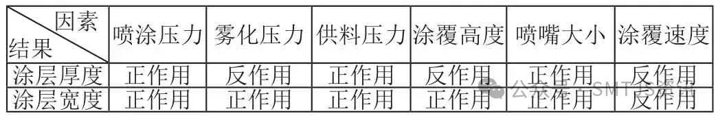
Table 2 Effects of Spraying Process Parameters on Coating
4. Common Problems and Solutions in Selective Coating
Below are some common coating problems and solutions summarized from our experimental work.
If coating solidification occurs during spraying, reduce the supply pressure or spraying pressure to decrease the amount of coating per unit volume at the outlet, ensuring that the coating at the spray valve outlet can be quickly sprayed onto the circuit board, preventing solidification or clogging of the nozzle due to coating accumulation at the outlet.
When the coating is too thick, the following methods can be used to resolve it: increase the spraying speed, reduce the supply pressure, increase the spraying height, or increase the spraying width (the stepping interval between two rows of coating layers is generally 4mm-12mm). When the coating is uneven with significant thickness variations, consider the following: if the flatness of each local area after spraying is good, the possible reasons are that the circuit board itself is warped or uneven, or there is dirt on the conveyor chain causing the circuit board to be unlevel, or the equipment itself is not level; if the overall flatness after spraying is uneven, in addition to the above possible reasons, another reason could be insufficient coating, which should be addressed by increasing supply pressure, reducing spraying speed, or reducing spraying width.
If there are many bubbles on the coating surface and the sizes of the bubbles are relatively uniform, they may partially disappear when cured at room temperature. This situation is likely due to insufficient coating, allowing air to penetrate the thin coating layer. To improve this, increase supply pressure, increase spraying pressure, or reduce spraying height. However, if the diameter of the bubbles or voids is large or if they only appear in localized areas, consider whether the circuit board itself is unclean, whether there are impurities in the supply tube, or whether the coating itself has impurities. Another possible cause of bubbles is when the spraying width is small (e.g., less than 5mm), and the subsequent coating overlaps with the previous coating, which can trap air in the surface of the previously sprayed coating, leading to bubble formation. This can be resolved by increasing spraying width, reducing coating amount, or increasing spraying speed.
If the coating surface has obvious spraying marks (e.g., alternating peaks and valleys), it is generally due to insufficient coating amount. This can be resolved by increasing spraying pressure or lowering spraying height to increase the spraying amount, thereby eliminating the spraying marks and improving spraying uniformity.
If the sprayed coating is discontinuous, consider the following possible reasons: whether there are foreign objects or large coating particles in the supply tube; whether there is air in the supply tube or coating overflow; whether the spray valve outlet is blocked, etc.
5. Application of Spraying Equipment
Traditional equipment for spraying three-proof treatment usually involves spraying unit boards and allowing them to air dry naturally. However, this process results in a longer cycle for three-proof treatment, low production efficiency, and is not conducive to mass production. Choosing suitable spraying equipment is crucial for improving the efficiency of three-proof treatment. Below, we introduce the application of selective coating systems and UV curing equipment, as shown in Figure 1.
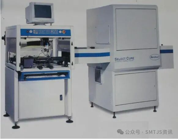
Figure 1 Selective Coating System and UV Curing Equipment
The selective spraying equipment can be used for three-proof protective coating of various single-sided, double-sided, and mixed circuit boards containing plugs, adjustable capacitors, high-frequency devices, potentiometers, and electrostatic sensitive components, suitable for protective spraying of different batch sizes and types of circuit boards. This equipment features multiple coating methods such as point, line, and area coating, with functions for selective coating over large areas or small regions, teaching programming, process parameter settings, and laser point-assisted positioning, capable of storing multiple sets of coating programs and process parameters, with the system automatically completing the entire coating process. The spraying valve consists of a spray valve and a dot coating valve. The spray valve completes large area coating; the dot coating valve is used for small area coating in hard-to-reach spaces, and it can rotate and pivot to coat the circuit board from different angles and directions.
UV curing equipment, when paired with relevant technology, can instantaneously ignite the UV lamp tube with high voltage, emitting ultraviolet light with a peak wavelength of around 360 nanometers. When irradiated on the UV coating layer, it can basically trigger curing of the coating in about 1-2 seconds.
The selective coating system and UV curing equipment form an integrated three-proof treatment system, where the coating equipment processes the circuit board for three-proof treatment and then directly sends it to the UV curing equipment for curing, which not only meets various spraying needs but also improves the efficiency of three-proof treatment.
6. Conclusion
The spraying process and spraying equipment are inseparable; the organic combination of process and equipment can provide users with a complete three-proof protection process solution.
 AD
AD