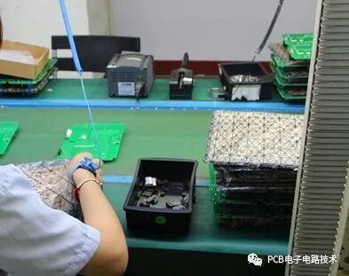
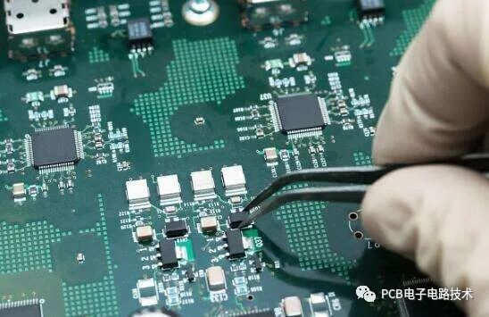
Based on years of experience in the maintenance and analysis of PCBA, we have categorized the maintenance methods into seven major types. Today, we will not conduct a detailed analysis of the PCBA circuit diagram, but rather provide a general overview of several methods we frequently use in repair analysis, as follows:1. Visual InspectionVisual inspection is the foundation of all maintenance. When we receive a faulty PCBA, the first thing we need to do is conduct a comprehensive visual inspection of the PCBA to check for broken connections, opens, shorts, cold solder joints, missing components, multiple components, incorrect components, lifted pads, component displacement, tombstoning, discoloration, deformation, or burn marks, etc. It is especially important to check the back of the PCBA for solder bridges. Additionally, we should verify whether the defective PCBA has been repaired, whether the BGA solder joints are consistent, and whether there are signs of soldering iron movement in other areas. Visual inspection is the first and very important step in repair analysis.Many people often overlook this point. When a faulty PCBA is received, they are eager to start checking with multimeters, oscilloscopes, and other testing tools. After spending a lot of time identifying the problem, they realize that the issue could have been easily resolved with a simple visual inspection, and by then, it is too late to regret. Most long-term repair and failure analysis personnel have had these experiences and lessons. In fact, some PCBAs have been under repair for several days without any clues. Ultimately, the problem is often resolved visually, albeit unconsciously. Therefore, it is crucial to pay special attention to this point in actual repair analysis to avoid unnecessary detours.
2. Comparative Method
As the saying goes: without comparison, there is no distinction. Comparison is also a maintenance technique we frequently use. When we notice some signal or value deviations during maintenance but are unsure if they are abnormal, the best approach is to take a good part for control measurement. Sometimes, to obtain stronger evidence, we tend to compare several parts.
Comparison can be divided into the following aspects:
1. By measurement method:
A. Comparison of resistance measurements; B. Comparison of voltage and waveform measurements; C. Comparison of current measurements.
2. By appearance:
A. Comparison of multiple and missing components; B. Comparison of incorrect components; C. Comparison of the same component from different manufacturers.
3. By functional testing:
A. Comparison of functional tests at different stations; B. Comparison of good and defective product functional tests; C. Comparison of functional tests with different specifications of fixtures; D. Comparison of functional tests with different external devices.
Comparison is a shortcut that can help us quickly identify problems. By comparing different repair methods, we can accurately and promptly find the key issues.
3. Touch Method
Strictly speaking, the touch method, also known as the temperature sensing method, involves directly feeling the temperature of the chipsets or other components on the PCBA with your hand to intuitively judge whether the PCBA is functioning normally.
This method can be used in actual maintenance analysis and functional testing on the production line. During the PCBA production process, for those devices that are hot but pass functional tests, we have an example where operators touch the device to determine the quality of the PCBA.
In the process of repairing and analyzing faulty PCBAs, we often have the experience that we cannot find the true cause of certain issues. However, when our hands unconsciously touch some BGAs or chips, we feel that they are hot and quickly heat up.
4. Hand Pressure Method
When repairing some faulty PCBAs, especially unstable ones, we may encounter issues that cannot be measured while measuring signals. At this point, we can apply hand pressure to some chips on the PCBA, mainly BGA encapsulated components, to see if it resolves the issue!
If it works, we can say redokbga or try replacing this chip. The hand pressure method is mainly suitable for issues like BGA opens, cold solder joints, or solder cracks. It can be used for powered tests and normal resistance value tests. Its advantage is that it can reduce the cumbersome steps related to measurement and maintenance, significantly shortening maintenance time.
The hand pressure method also has certain stress implications. For a seasoned repair analyst, the force applied when pressing the PCBA should be appropriate. Do not apply excessive force, and do not lift one end of the PCB while pressing the BGA to avoid breaking or disconnecting the PCB.
When testing for cold solder joints on a BGA, it is essential to press down on the top of the BGA for better results.
When a signal connects between two BGAs, and we measure its resistance (diode value or resistance value) to be too high, and there are no other components in the circuit to open, how do we determine which BGA has poor soldering? At this point, we can first take a simple and effective method, which is to press down on the two related BGAs. When we press the BGA, its resistance returns to normal, indicating a poor soldering point.
Pressing from different directions repeatedly to obtain results. Once or twice may not yield significant effects, but do not lose heart. Repeated attempts and pressing multiple times will quickly lead you to the answer.
It is worth noting that we can determine certain BGA opens or cold solder joints through manual pressure, but not all opens or cold solder joints can be identified this way.
5. Open Circuit Method
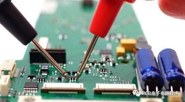
The open circuit method is a common technique for measuring the resistance values of PCBA components. The so-called open circuit method refers to disconnecting the circuit and inspecting it individually. It is usually used to determine cold solder joints, opens, partial short circuits, or points with excessively high or low resistance values.
During the process of disconnecting the circuit, we sometimes need to remove some resistors, inductors, transistors, or other components, and sometimes we need to lift the pins of some chips. Eliminating the parasitic resistance near the chip to measure the upper limit signal is a typical application of the open circuit method.
It must be emphasized that when some signals connect between BGAs, and there are no small sections in the circuit for us to disconnect, we must not cut the PCB traces to find unauthorized fault points.
Due to the company’s strict appearance requirements for PCBA products, not only do we fail to eliminate faults, but we also spend a lot of time taking unnecessary detours, sometimes even scrapping the PCBA due to excessive rework on BGAs.
In daily maintenance operations, the above examples are often popular and not uncommon.
As an excellent repair analyst, every step must be guided by rigorous logical thinking and accurate judgment, with a clear mind, organized thoughts, and orderly analysis to achieve maximum efficiency.
6. Cleaning Method
As the name suggests, this method involves removing dirt from the PCBA.
Some defects on the PCBA, such as excessive battery leakage current or poor functional testing of other external devices, can be visually inspected for suspicious areas for solder debris or other contaminants before measuring or replacing components. If necessary, cleaning can have remarkable effects on certain defects.
7. Replacement Method
The replacement method we mentioned refers to the maintenance approach taken when resistance, voltage, or waveform measurements are ineffective, as not every defective PCBA can be intuitively detected with testing tools.
The replacement method also has certain principles. We can decide which components to replace first based on our understanding and maintenance experience of various PCBAs. Additionally, measurements of some critical signal points can also serve as the basis for our replacements.
In actual maintenance, for PCBAs that are currently difficult to identify defects, our replacement is a typical application of the replacement method.
As mentioned earlier, we only use the replacement method when we genuinely cannot find the problem point. However, in actual maintenance, we should not replace BGAs or other chips without thoroughly checking the relevant circuits due to laziness or temporary negligence. This often affects functionality.
Moreover, excessive magnetic flux can also cause excessive battery leakage current. Of course, some excessive magnetic flux can be detected with a multimeter. We should not forget this during maintenance.
In summary, the methods for maintaining and analyzing PCBA are diverse. We must not only master various maintenance and analysis methods but also learn to apply them flexibly. For beginners, this is not something that can be achieved overnight. We must remain calm, work hard, avoid arrogance and impatience, and maintain a humble mindset to achieve success.
I hope this article can provide you with some assistance!