Similarities and Differences between Cold Soldering and Open Soldering1.Similarities
Cold soldering and open soldering exhibit many similarities in their manifestations, which often leads to misidentification in practical work. Therefore, accurately identifying the similarities and differences between cold soldering and open soldering is crucial for quality control in electronic product manufacturing.
The similarities between cold soldering and open soldering mainly manifest in the following aspects:
1)Both cold soldering and open soldering result in joint failures characterized by interface failures, meaning that poor electrical contact or micro-cracks occur at the interface between the pad and the solder;
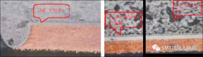
2)The definitions of cold soldering and open soldering are similar, as they both fail to form the necessary intermetallic compound layer (referred to as the interface alloy layer or IMC), as shown in Figures 19 and 20;
3)In engineering applications, the effects and hazards are similar, namely: both exhibit poor electrical contact, unstable electrical performance, and weak connection strength. This is particularly true for BGA and CSP components, where such solder joint defects can remain hidden for a short period of days or extend to months or even years before becoming apparent.
2.Differences and Physical Localization1)Different formation mechanisms:
Open soldering occurs when the surface of the soldered metal is oxidized, sulfided, or contaminated, rendering it unsolderable, while cold soldering is caused by insufficient heat supplied during the soldering process.
2)Different solutions:
Open soldering can generally be resolved by improving the cleanliness and solderability of the soldered metal surface and adjusting the chemical activity of the flux, making it relatively easy to achieve. In contrast, cold soldering requires addressing the issue of sufficient heat supply during the soldering process, especially for high-density components like BGA and CSP, which often involves the heating methods of the reflow oven and the efficiency of heat transfer. Therefore, it is more widespread and challenging.
3)Differences in connection strength:
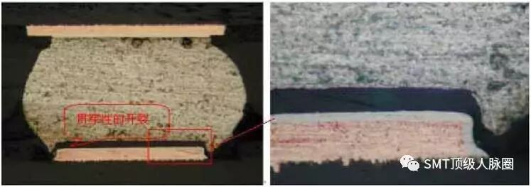
In open soldering, the solder is separated from the base metal surface by an oxide layer, resulting in poor adhesion of the solder after solidification and weak connection. In cold soldering, the IMC layer formed at the interface of a slightly defective solder joint is very thin and poorly developed, while in more severe cases of cold soldering, it is often accompanied by penetrating cracks, resulting in no strength at all, as shown in Figure 21.
4)Differences in metallographic structure:
The metallographic structure of open soldering slices is relatively dense, as shown in Figure 22; while the metallographic structure of cold soldering slices is uneven, as shown in Figure 23.
)Differences in micro-optical visual images:(1)Visual images of good solder joints:
①CBGA
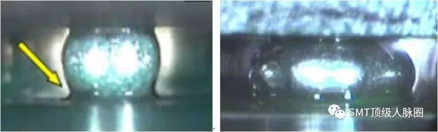
During reflow soldering of CBGA, since the solder balls do not melt, the solder paste fills and wets sufficiently between the pad and the solder balls, resulting in a good wetting angle, smooth and flat surface, and no collapse in height, as shown in Figure 24.
②PBGA
The surface of spherical solder joints is bright and smooth, with a good wetting angle, and the collapse height is about (1/3 to 1/2) of the height of the spherical pins. As shown in Figure 25.
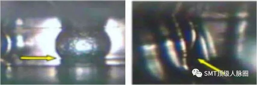
The micro-optical visual image of solder joints shows that the solder joint has not formed a wetting fillet, as shown in Figure 26.
1.Cited Standards and Literature
1)QJ Aerospace Standards
There is no unified definition of several electronic assembly soldering defects both domestically and internationally, which has led to many complications. Zhang Yongzhong from the Aerospace Second Academy said: “Regarding the understanding of open soldering, my view is also based on intermetallic compounds. The Science and Technology Group also published a special issue on open soldering in 2013, which was distributed to various units in the form of a quality bulletin, where the definition of open soldering referenced the QJ standard but also extended it, dividing it into explicit open soldering (also called broad open soldering) and implicit open soldering, where explicit open soldering can be visually inspected.”The QJ standard mentioned by Zhang Yongzhong is the QJ2828 “Terminology of Electronic Assembly” proposed by the Aerospace 708 Institute, which was formulated with reference to NASA standards and US military standards, and is still valid today.
2)IPC Standards of the United States
I also reference the IPC standards of the United States here. It should be noted that the IPC standards are commercial standards formulated by the “IPC Association Connecting Electronics Industries”.
The IPC-A-610ECN “Acceptability of Electronic Components” published in April 2010 summarizes soldering defects in section 5.2 as: exposed metal substrates, pinholes/blowholes, incomplete solder paste reflow, non-wetting, cold soldering/rosin solder connections, de-wetting, solder balls/solder splashes, bridging, solder mesh/solder splashes, solder disturbance, solder cracking or cracking, solder spikes, lead-free filling warping, and lead-free thermal tearing/contraction, totaling fourteen categories, which is not exhaustive.
3)Professor Fan Rongrong’s Works
I will also reference Professor Fan Rongrong’s definitions of several soldering defects; Professor Fan Rongrong is a leading figure in China’s electronic assembly industry and a holder of seven United Nations patents, recognized as an outstanding young and middle-aged scientist in China in the 1980s.
2.Misunderstanding of Soldering Defect Definitions
Open soldering actually only refers to the “open” in IPC, but IPC-A-610E does not mention open soldering, nor does it mention “open”; “open” means an open circuit, and while there is a term for “open circuit” in China, it is not included in the soldering defects of IPC-A-610E.
Non-wetting, false soldering, open soldering, open circuits, open soldering… some belong to “colloquial terms” rather than technical terms, and each has different definitions.
Open soldering is not equivalent to an open circuit; the fundamental characteristic of open soldering is that the intermetallic compound does not meet the requirements; an open circuit may not necessarily be caused by open soldering, for example, a “standing monument” is also an open circuit, but it is not open soldering; non-wetting and open soldering have different meanings, but non-wetting will inevitably lead to open soldering; open soldering is not a derivative phenomenon in China, but an objective fact.
3.Open Soldering
1)In cases where all soldering parameters (temperature, time) are normal, any phenomenon during the soldering process where an appropriate thickness of intermetallic compound (IMC) is not formed at the connection interface can be defined as open soldering.
——Fan Rongrong, “Modern Electronic Assembly Engineering Applications 1100 Questions”, 2011.
2)The definition of open soldering in QJ2828 is:
Open SolderingPseudosoldering
The solder and the metal surface of the soldered part are isolated by oxidation or other contaminants, failing to form a metal alloy layer, merely adhering to the surface of the soldered part, resulting in defects.
)In soldering, if the solder does not reach the minimum required wetting temperature between the solder and the base metal; or if local wetting occurs but the metallurgical reaction is incomplete, it can be defined as cold soldering.
——Fan Rongrong, “Modern Electronic Assembly Engineering Applications 1100 Questions”, 2011.
2)The definition of cold soldering in QJ2828 is:
False Soldering (Cold Soldering)Cold Solder Joint
When the soldering temperature is too low, the solder may solidify before wetting and flowing, resulting in a solder joint appearance that cannot be smooth and shiny, which is a defect worse than open soldering.
3)The definition of cold solder joints in IPC-610D is:
Cold solder joints refer to those exhibiting very poor wettability, grayish appearance, and loose solder joints. (This phenomenon is caused by excessive impurities in the solder, insufficient cleaning before soldering, and/or insufficient heat during the soldering process.)
4)The definition of cold solder connections in IPC-T-50 is:
Solder connections exhibit poor wettability and a gray, porous appearance. (This is due to excessive impurities in the solder, insufficient cleaning before soldering, and/or insufficient heat during the soldering process.)
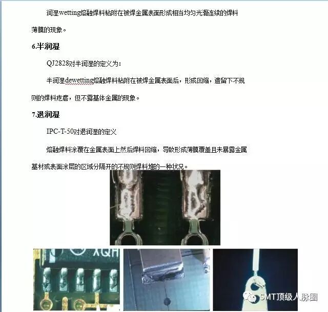
Solder connections exhibit poor wettability, which may show signs of retained rosin, leading to separation of the surfaces to be connected.5.Wetting
The definition of wetting in QJ2828 is:
5. Conclusion
After nearly forty years of rapid development, the understanding of the importance of quality and reliability in SMT has gradually deepened among industry professionals. The soldering and inspection technologies for SMT assembly have rapidly advanced; however, the lag in standards, including various definitions and terminologies, has already affected the development of the SMT industry. The existing terminology standards related to electronic assembly in China were basically introduced in the mid-1990s, while the terms and definitions in IPC standards also have certain issues and are not entirely suitable for China’s national conditions.
As a result, it is normal to encounter different understandings of terms and definitions. We hope that China’s standards can meet the needs of manufacturing development.
For reference only.