In the world of PLCs, all signals can be divided into two main categories: Digital and Analog. They are the “left hand and right hand” of PLCs in perceiving and controlling the external world, and understanding the difference between the two is crucial.
1. Digital: The Black-and-White ‘Switch’ Signal
-
Core Characteristics: There are only two states: ON (1) or OFF (0). Like a switch, there are only two possibilities: “on” and “off”, with no intermediate state.
-
Common Devices:
-
Input: Buttons, switches, proximity sensors, photoelectric sensors (detecting presence), etc. They provide the PLC with signals of “on” or “off”.
-
Output: Relays, contactors, indicator lights, solenoid coils, etc. The PLC controls them using commands of “energize” or “de-energize”.
-
Advantages: Strong anti-interference capability, stable signals, and simple processing.
-
Analogy: Like a light switch, which has only two states: on and off.
2. Analog: The Continuously Varying ‘Proportional’ Signal
-
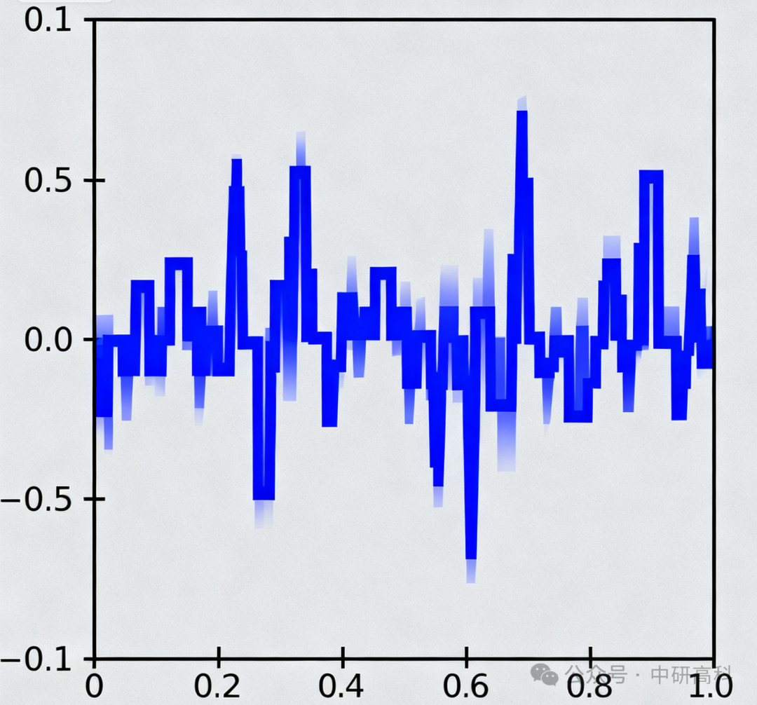
Core Characteristics: Its signal magnitude is a continuously varying value. This value can reflect the magnitude of physical quantities such as temperature, pressure, speed, and flow.
-
Common Devices:
-
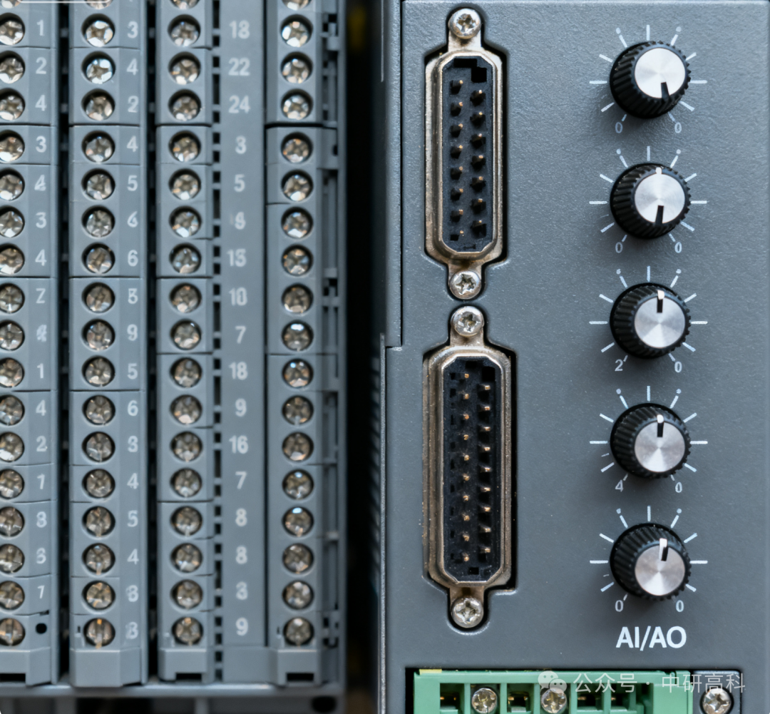
Input: Temperature transmitters, pressure sensors, level sensors, flow meters, etc. They convert physical quantities into standard electrical signals (such as 4-20mA current signals or 0-10V voltage signals) sent to the PLC.
-
Output: Proportional valves, frequency converters, servo drives, electric control valves, etc. The PLC precisely controls their opening, speed, etc., by outputting a continuous analog signal.
-
Advantages: Capable of transmitting precise numerical information for accurate control.
-
Disadvantages: Prone to electromagnetic interference in the field, requiring proper shielding.
-
Analogy: Like a faucet, which can be adjusted to any opening between “fully closed” and “fully open” to control the flow of water.
3. Core Differences and Connections
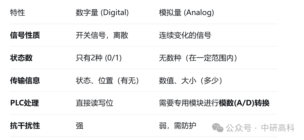
4. How to Use Analog Signals in Programs? The PLC’s CPU can only process 0 and 1 and cannot directly understand the 4-20mA current. At this point, an analog input module is needed.
Its functions are:
-
Collection: Receiving the 4-20mA current signal from the sensor.
-
Conversion (A/D Conversion): Converting this continuous current signal into a corresponding digital value (for example, for a 16-bit module, the converted value may be 0-27648).
-
Calibration: In the program, you need to use a conversion formula to convert this 0-27648 digital value back to the actual engineering value (for example, 4mA corresponds to 0°C, 20mA corresponds to 100°C, so the digital value of 13824 corresponds to 50°C).
Conclusion: Digital signals are used to handle the “yes or no” questions, while analog signals are used to handle the “how much” questions. They are the foundation of the perception and control layers of automation systems, complementing each other and are indispensable.