In the world of industrial automation, from the precise assembly of automotive production lines to the efficient sorting in smart warehousing, and to the safe temperature control in chemical workshops, all rely on the “intelligent brain” of the PLC (Programmable Logic Controller) operating silently in the background. One of the core mechanisms that supports this “brain” in making efficient decisions and executing accurately is the often-overlooked yet crucial PLC scanning cycle. Through some single button start/stop cases, we will help you understand the mechanism of the scanning cycle.
[Action Description]
Single button start/stop control refers to a scenario where pressing the button for the first time triggers output Y and maintains self-locking; pressing it a second time releases the self-lock. Subsequent presses of the button repeat steps 1 and 2.
This action seems very simple, but there are many ways to write the program, with at least 40 different methods possible; however, this is not the focus. The key is to learn certain methods that can help us understand the scanning process of the program. Therefore, starting from this lesson, we will explain various single button start/stop programs and analyze their scanning cycles.
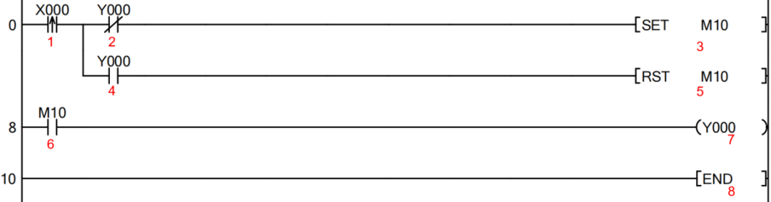
The program is shown in the figure below.
[Scanning Cycle Analysis]
When the button is pressed for the first time:
The program scans the first cycle from top to bottom. In the first step, the rising edge of X0 is activated; in the second step, Y0 normally closed is activated; in the third step, the set instruction sets M10; in the fourth step, Y0 normally open is deactivated; the reset instruction in the fifth step is not executed; in the sixth step, the normally open contact of M10 is activated because M10 is set; in the seventh step, Y0 has output; finally, the eighth step END is scanned, and the program scan ends; output refresh is executed, with M10 and Y0 having output.
The program scans the second cycle from top to bottom. In the first step, the rising edge of X0 is not activated (the rising edge can only activate for one scanning cycle); the actions in steps 3 and 5 are not executed; in the sixth step, the normally open contact of M10 is activated because M10 is set; in the seventh step, Y0 has output; finally, the eighth step END is scanned, and the program scan ends; output refresh is executed, with M10 and Y0 having output.
The subsequent scanning cycles of the program have the same output effect as the second cycle (M10 and Y0 have output).
When the button is pressed for the second time:
The program scans the first cycle from top to bottom. In the first step, the rising edge of X0 is activated; in the second step, Y0 normally closed is deactivated (because Y0 was set during the first button press); in the third step, the set instruction is not executed; in the fourth step, Y0 normally open is activated; in the fifth step, M10 is reset; in the sixth step, the normally open contact of M10 is deactivated; in the seventh step, Y0 has no output; finally, the eighth step END is scanned, and the program scan ends; output refresh is executed, with M10 and Y0 having no output.
The program scans the second cycle from top to bottom. In the first step, the rising edge of X0 is not activated; the actions in steps 3 and 5 are not executed; in the sixth step, the normally open contact of M10 is deactivated; in the seventh step, Y0 has no output; finally, the eighth step END is scanned, and the program scan ends; output refresh is executed, with M10 and Y0 having no output.
The subsequent scanning cycles of the program have the same output effect as the second cycle (M10 and Y0 have no output).
Pressing the button again will continue to repeat the actions of the first and second button presses.
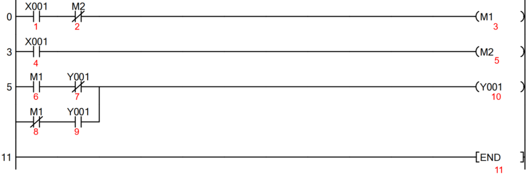
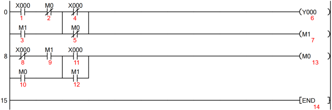
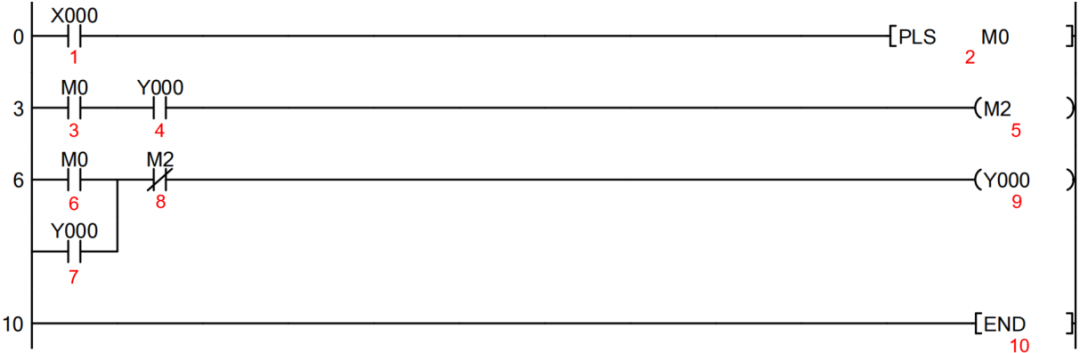
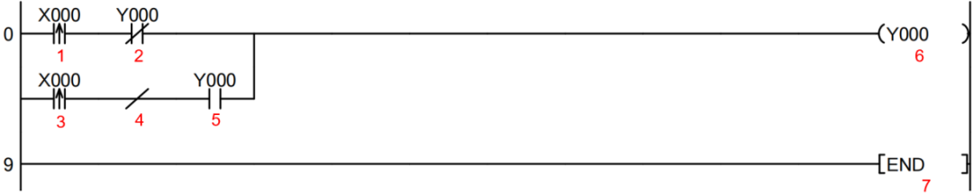
Below, we will share more single button start/stop controls. The order of program scanning has already indicated that you can analyze the scanning process yourself.
Case 2
Case 3
Case 4
Case 5
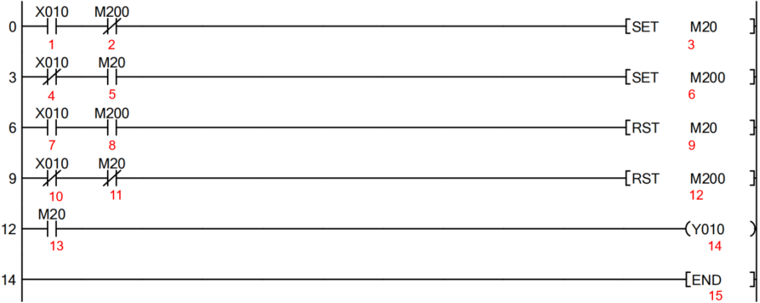
Case 6

 Scan the code to obtain the most comprehensive Mitsubishi/Siemens PLC case programs. The editor has worked hard to compile these programs, so if you need them, be sure to save them for future reference!