

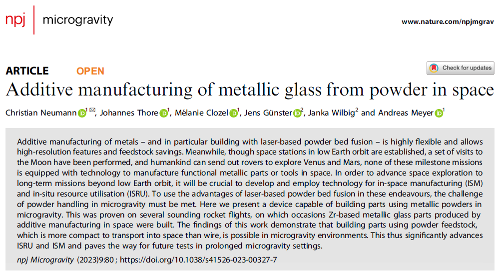
Introduction
Additive manufacturing (AM) technology seems to offer significant opportunities to meet the demands of space flight, as it helps save materials, reduce transport weight, and shorten production time. Additionally, it supports the use of recycled materials or materials collected directly on-site, known as in-situ resource utilization (ISRU). Over the past decade, NASA and space manufacturing companies have sent fused filament fabrication (FFF) printers to the International Space Station, demonstrating the feasibility of polymer additive manufacturing in microgravity environments.
Laser-based powder bed fusion technology (PBF-LB) is one of the most versatile additive manufacturing processes in terms of achievable geometries and scalable process parameters, and it is applicable to a variety of materials, including metals, ceramics, glass, and polymers. The process involves spreading a flowable powder on a build platform and then melting it with a laser according to a selected two-dimensional geometry. Subsequently, the platform lowers, and a new layer of powder is spread over the already formed powder layer. In recent years, this technology has matured and become a reliable alternative for manufacturing structural components, especially for parts with complex geometries or materials that are difficult to process using traditional methods.
Metallic glass is a relatively new class of materials, with its history dating back to the early 1960s. Depending on the composition, they exhibit some outstanding properties, such as excellent corrosion resistance, good mechanical properties, and low friction coefficients. NASA’s BMGG project (Bulk Metallic Glass Gear project, https://www.nasa.gov/directorates/spacetech/gamechangingdevelopment/projects/BMGG, last accessed: January 18, 2023) aims to develop gearboxes made from bulk metallic glass (BMG), which do not require lubrication or heating, showcasing the application potential of such materials. Despite the numerous advantages of bulk metallic glass and significant improvements over the past decades, the main obstacle to using it as structural components and tools is the limited size of manufactured parts. During the casting process, as thickness increases, cooling rates decrease and crystallization intensifies, typically limiting thickness to a few millimeters to centimeters. Only recently have these materials been applied in additive manufacturing. By stacking glassy layers layer by layer, this process has proven capable of breaking through these size limitations and forming thicker amorphous parts than casting.
Therefore, both bulk metallic glass and laser-based powder bed fusion technology possess characteristics attractive for aerospace applications. However, there has been little research combining the two for aerospace applications. To integrate these two fields, i.e., to use bulk metallic glass to manufacture parts in a powder-based process independent of gravitational environments, there are various options for experiments under microgravity conditions, with the duration of microgravity gradually increasing: drop towers (microgravity time typically less than 10 s, residual acceleration about 10-4 g), parabolic flights (about 20 s per parabolic flight, approximately 10-3 g), sounding rockets (about 400 seconds, 10-4 to 10-6 g), and orbital platforms (hours to months, 10-3 to 10-5 g).
Sounding rockets achieve a good balance between availability, cost, and microgravity time, thus being selected as the experimental environment after the system was validated for microgravity applications through parabolic flights. We believe that sounding rocket flights are a necessary transitional phase in the development of in-orbit additive manufacturing equipment, which will provide sufficient microgravity time for producing functional metal parts.
Methods
Payload for Sounding Rocket Flight
Therefore, this study aims to utilize laser-based powder bed fusion technology to additively manufacture metallic glass parts in a microgravity environment, specifically using powder feedstock. The choice of laser-based powder bed fusion process is due to its flexibility. On Earth, the laser-based powder bed fusion process typically relies on gravity to keep the powder layer in contact with the build platform. Thus, handling powder feedstock becomes the biggest challenge in reduced or zero gravity. To address this issue, Zock et al. developed an airflow-assisted powder deposition technique, which combines a porous build platform with low pressure generated by a vacuum pump, allowing gas to flow through the build platform to stabilize the powder. This powder handling system has been tested and improved during multiple zero-gravity parabolic flights at the German Aerospace Center (DLR) and the European Space Agency (ESA), but so far, laser melting operations have not been conducted in microgravity environments.
On the other hand, sounding rocket flights can provide several minutes of microgravity time, which is sufficient to deposit multiple layers of powder and melt specific shapes with a laser. Therefore, the Space Materials Physics Institute at the German Aerospace Center designed and manufactured a device capable of processing powder and manufacturing parts in a microgravity environment, based on the parabolic flight equipment developed by Zock et al., to validate the feasibility of this powder stabilization concept for the MAPHEUS sounding rocket.
To become a payload for the sounding rocket, the device underwent significant modifications based on the parabolic flight equipment. Among other aspects, the device needed to be smaller in size, withstand higher accelerations, have remote communication capabilities, and adapt to the vacuum environment of space.
For hardware that meets these requirements, the MAPHEUS sounding rocket can provide approximately 6.5 minutes of microgravity time during suborbital flights above 90 kilometers from the ground, with residual accelerations as low as 10-4 to 10-6 g, reaching altitudes of up to 260 kilometers. The MAPHEUS payload support system at the DLR mobile rocket base provides a bidirectional data communication interface and real-time video downlink for scientific payloads, allowing ground station operators to monitor the fully automated manufacturing process in real-time using telemetry technology and intervene manually via remote control commands when necessary.
Overall Experimental Device
The device must meet several requirements to operate normally on the sounding rocket. First are the environmental requirements: the device must conform to specific dimensions, withstand dynamic loads and vibrations during rocket launch, adapt to external vacuum conditions, stabilize powder in a microgravity environment, and be equipped with a cooling system independent of air convection. Most components are off-the-shelf and not designed to withstand rocket launch accelerations or operate in a vacuum environment. Therefore, all components must be modified to enhance mechanical strength, toughness, and vacuum resistance. Additionally, there are operability requirements: the device must be equipped with a powder container and build platform, and remain easy to operate even after the device enters flight configuration (i.e., physically connected to other parts of the payload and mounted on the launcher); it must be capable of recording process data within the device and transmitting it to ground monitoring personnel; and it must allow users to interrupt the manufacturing process in case of failure. Finally, the device must be equipped with an independent power supply and be capable of manufacturing parts in a sealed experimental chamber without human intervention.
The final design and manufactured device is named MARS-M (Multi-Material Additive Manufacturing Device for Research and Space Flight, compatible with MAPHEUS), as shown in Figure 1 (left), with a total length of 700 millimeters, a diameter of 438 millimeters, and a net weight of 44 kilograms, plus an additional 12 kilograms for the external structure of the rocket payload. It includes a compact, lightweight, fully automated Cartesian coordinate additive manufacturing device, encompassing control computing, data acquisition and processing, powder stabilization, and power supply functions.
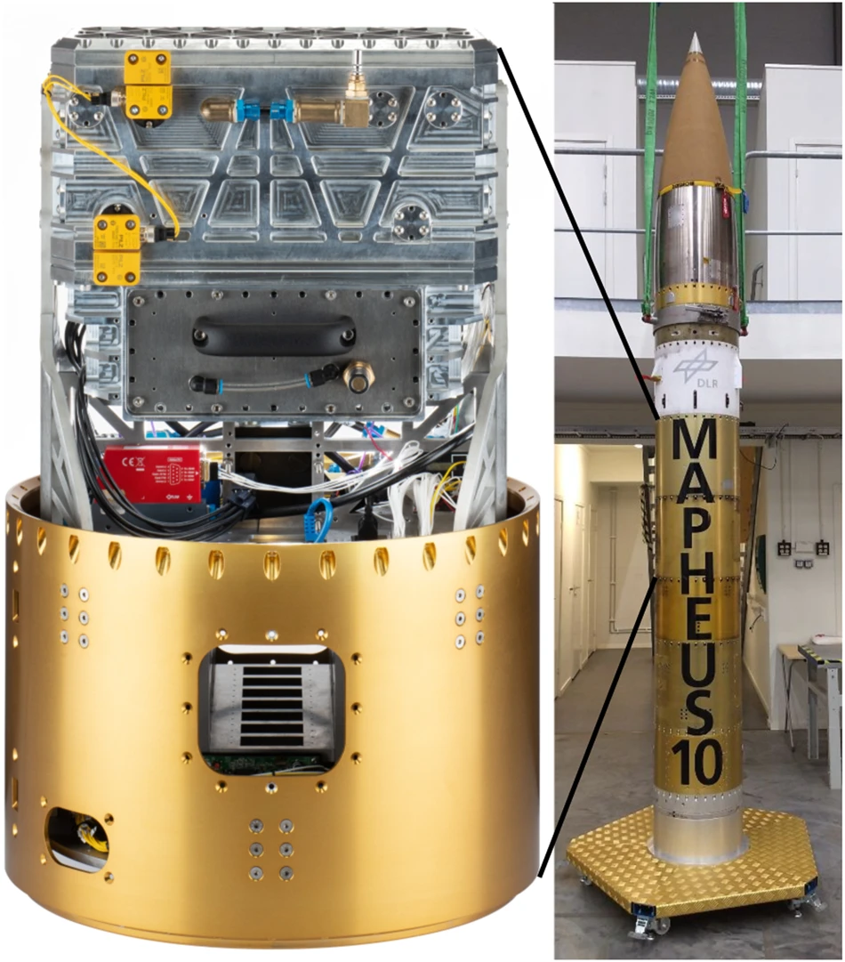
Fig. 1: MARS-M rocket payload module.MARS-M (left) and the MAPHEUS-10 rocket payload (right) of which it is part.
Motion Mechanism
In addition to providing the necessary operational steps for part manufacturing (laser scanning, powder spreading, and build platform movement), the basic mechanical device must also have sufficient strength to withstand static and dynamic loads during different phases of flight. To meet these two requirements, the device adopts a Cartesian coordinate system, with components consisting of X and Y axes used to move the focused laser spot in the horizontal plane above the build platform, while the vertical Z axis lowers the build platform as the part thickness increases (see Figure 2). An additional E axis is set up for laying down new powder layers. Both the X and Y axes use 8-millimeter diameter shafts and self-lubricating dry-running polymer bearings as linear sliders to prevent powder particles from adhering to lubricants and obstructing movement. To reduce weight, the shafts are made of carbon fiber reinforced polymer (CRP) and hard-anodized aluminum materials. Each axis is driven by stepper motors through synchronous belts, and optical limit switches restrict the range of motion. The Y axis drives the X axis, which in turn moves the holder equipped with fiber-coupled laser optical components. The E axis for powder spreading uses similar dry-running bearings and linear sliders as the X and Y axes, driven by stepper motors through two threaded rods synchronized by synchronous belts. This axis is parallel to the X axis and is equipped with optical limit position sensors. The Z axis adapter carrying the build platform can move up and down, driven by three fine threaded rods, which are also synchronized by synchronous belts and driven by stepper motors, while using an optical position switch to determine a fixed reference position.
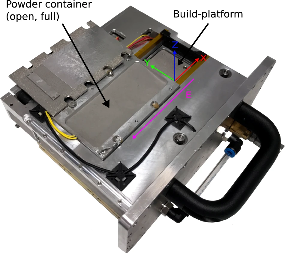
Fig. 2: Cartridge holding the build-platform (here, clear of powder) and the powder container.
Laser System: Light Source, Optical Components, Drivers
Like the other parts of the device, the laser system must withstand various forces experienced during flight and must be equipped with a cooling system independent of air convection. The laser system consists of a fiber-coupled diode laser as the light source, laser optical components connected to the fiber end, diode driver electronics, and a laser cooling system. For the selective laser melting process, we use a Coherent IS58 diode laser bar module, which can output a maximum optical power of 283 watts at a center wavelength of 976 nanometers to a 100-micron fiber core. The laser optical components are assembled using standard C-type lens adapters, SMA-type fiber adapters, and plano-convex lenses. All 1-inch lenses are λ/10 grade uncoated fused silica lenses (Edmund Optics). The distance from the front lens focal plane to the top layer of the formed part is 35 millimeters, resulting in a minimum laser spot diameter of 80 microns. A temperature sensor is installed on the optical component assembly to quickly detect any overheating, which is mostly caused by dust accumulation. The laser diode driver used is the MSM 100 – 25 model from MESSTEC. The system also features interlock circuits and other critical safety devices to prevent laser emission when the cabin door is open, ensuring the entire device complies with Class 1 laser system standards. Typically, laser diodes require cooling through constant temperature and current cooling water, but this is nearly impossible to achieve in the compact payload of a sounding rocket. Therefore, we specifically designed an alternative cooling solution. The cooling circuit uses a pump to circulate the cooling liquid and transfer heat to a specially designed heat exchanger. The heat exchanger transfers thermal energy from the cooling liquid to the phase change material Rubitherm RT28 HC. This allows the laser to operate at full power for a limited time of 10 minutes, which is entirely sufficient for experiments conducted during limited microgravity time. However, in laboratory experiments, an external cooling system is used to achieve stable long-term operation of the laser.
Pressure Chamber and Airflow
The manufacturing process takes place in a closed, airtight environment within the experimental chamber to ensure a constant pressure environment, particularly maintaining an oxygen concentration of about 0.4% during processing. The design of the experimental chamber must withstand pressure differences between the inside and outside. On one hand, when vacuuming the experimental chamber, negative pressure is generated inside, requiring a pressure difference of up to 1 bar before purging with the desired gas composition; on the other hand, during space flight, as external pressure decreases, positive pressure is generated inside the experimental chamber, thus needing to withstand pressure differences of up to 2 bars.
The forming process occurs in a easily removable plug-in: this is a box-like component accessible through the cabin door (as shown in Figure 2), containing the powder container, Z-axis and E-axis drivers, and the build platform. In this way, the build platform, powder, or even the entire box component can be easily replaced while the device is in flight configuration and before launch. When the powder becomes part of the powder bed, it must remain stable in a weightless environment while having sufficient flowability to allow new powder layers to be laid down on the powder bed. To achieve this, a closed-loop airflow is used to push powder particles toward the build platform inside the box component, similar to the airflow-assisted powder deposition method described earlier. A rubber hose connects to the mounting adapter of the build platform to create a vacuum beneath the platform. Due to the porous nature of the platform, airflow is generated perpendicular to the surface, pushing powder particles toward the platform. Outside the box component, airflow passes through a set of 10-micron particle filters and a mass flow sensor (Red-Y series, Vögtlin Instruments GmbH) into two parallel working 3111.610 controllable diaphragm pumps (Boxer GmbH). The filters and flow sensors are installed outside the experimental chamber, while the pumps are installed inside the experimental chamber to avoid the pumps being affected by external pressure differences. The outlet of the pumps is open, allowing gas to flow back into the experimental chamber.
Build Platform and Powder Spreading
The MAPHEUS sounding rocket can provide 6.5 minutes of continuous microgravity time, which is sufficient for feasibility validation. Due to the limited time, the build platform does not need to be overly large, with dimensions selected as 45 millimeters × 45 millimeters, made from a 5-millimeter thick, 8-micron pore size 1.4404 stainless steel porous sintered body.
The control process for laying down a layer of raw material on the build platform is as follows: first, the Z-axis lowers to the specified layer thickness, adjusting the build platform to the appropriate position to receive the new powder layer. The Z-axis only performs a zeroing operation before laying the first layer of powder to pre-determine the reference position and calibrate according to the precise thickness of the build platform. After the Z-axis lowers the build platform, the build platform adapter moves along the E-axis to the powder storage container.
When starting to move, the piezoelectric actuator mounted at the bottom of the powder storage container is activated, causing the storage container to produce harmonic vibrations. The vibration frequency is adjusted to be close to the inherent frequency of the mechanical system to maximize energy transfer. In this way, the powder gains kinetic energy, and particles that might otherwise agglomerate are dispersed, improving flowability. Additionally, throughout the process, airflow through the build platform continuously acts, pushing powder particles toward the build platform. The filter at the top of the storage container allows gas from the experimental chamber to enter. The system sets a pause time to allow powder particles to settle, which usually takes a few seconds. Afterward, the E-axis moves the build platform back to the initial position beneath the laser optical components. During this movement, powder particles exceeding the set layer thickness are blocked, forming a flat powder layer with the specified thickness. The remaining raw material is left in a completely sealed compartment. It is particularly noteworthy that in a microgravity environment, any parts manufactured must consist of a framework structure made of single lines (curved or straight) to allow gas to pass through (see Figure 7 and Supplementary Figure 2).
Power Management
The device can be powered by an external power supply during laboratory use, but it must be equipped with an independent power supply when flying on the rocket. Therefore, it is designed to be powered by an external power supply through a umbilical connector on the ground, while during flight, it is powered by an internal battery. In the off state, for safety reasons, the payload can only be activated by applying 16 – 20 volts of direct current to the umbilical connector and cannot be powered by the battery. Lithium iron phosphate (LiFePO4) batteries (two sets, using a 6S3P configuration) can be installed or removed through a hatch and can be switched on and off individually. Their nominal capacity of 13.8 amp-hours can support the device for 30 minutes of operation at full power.
Process Control
To ensure smooth operation of the manufacturing process without overly relying on user control, the actual manufacturing process is driven by a controller board, which is equipped with interfaces for controlling stepper motors, laser power, and power switches, capable of reading and writing digital input signals and monitoring and controlling temperature. We use the Smoothieboard 5XC V1.1 controller board from the open-source hardware project Smoothieware.org. This board controls the stepper motors for the X, Y, Z, and E axes through onboard drivers, as well as the corresponding limit switches and position sensors.
Data Acquisition and Communication Interface
Since many parameter changes (such as temperature, airflow speed, axis position, etc.) and operations occur simultaneously during the additive manufacturing process, having a clear and comprehensive communication interface is crucial for monitoring parameters, recording processes, and gaining a comprehensive understanding of the situation, as well as being able to review the process after the experiment to identify potential sources of error. To monitor the manufacturing process and collect on-site data, we use a data logging system. This system is a modified Gigabyte GA-SBCAP3450 single-board computer running LabVIEW virtual instruments (National Instruments). The peripheral hardware used includes: two cameras and two analog and digital interface cards, connected via USB. The data logger connects the following sensors:
- High-definition camera for observing the overall condition of the build platform;
- Microscope for detailed observation of Z-axis movement;
- Sensor for recording battery and external power supply voltage;
- Pressure sensor for measuring internal pressure in the experimental chamber, with a measurement range of 0 – 5 bars;
- Mass flow sensor for measuring airflow through the build platform, with a measurement range of 0.3 – 15 liters/minute;
- Pt1000 temperature sensors installed on the laser diode, laser optical components, and build platform;
- Inclination sensor capable of reading data within ±1g in the Z-axis direction, useful for detecting microgravity conditions;
- Rothmann electronic O2S-FR-T2 oxygen sensor for measuring internal oxygen concentration in the experimental chamber, with a measurement range of 0.1% – 25%;
- Digital input sensors for reading launch events and microgravity start and end signals (provided by the MAPHEUS service system).
All sensor data, machine status, telemetry and remote control command data, and any error messages are recorded in an onboard file, with a recording frequency typically of 10 Hz, which can be easily increased to 100 Hz or higher if necessary. Video recording frame rate is 30 frames/second. The data logger sends telemetry data streams and video signals and receives remote control command data packets. Data transmission with the MAPHEUS service module occurs via bidirectional RS485 serial communication according to predefined interface protocols. The transmitted video signal can display real-time images captured by the cameras and microscope, along with some of the most important sensor data and system status information. Remote control command data packets received from the ground station are checked, parsed, added to the log file, and executed immediately.
Ground Station and Ground Support Equipment
Although the device is designed to operate without external assistance or additional equipment during flight, some large equipment is still needed for preparation before launch. Therefore, to reduce weight, these ground support equipment (GSE) are typically not integrated into the payload. These devices are placed in protective boxes near the launcher or mounted on the launcher. In this project, the ground support equipment includes: power supply, Ethernet interface, vacuum pump, valves, gas cylinders, and pressure sensors. The power supply connects to the payload via the umbilical connector, and before launch, power switches to the internal battery. The ground station for the MARS-M project is a desktop computer running LabVIEW virtual instruments. It receives telemetry data and video downlink signals and sends remote control command data packets based on user input. Data, flight events, and video are displayed to operators and recorded in files. Additionally, the ground station is connected to the ground support equipment via Ethernet. Before launch, this Ethernet connection is connected to the Smoothieboard controller board, data logger, and Ethernet interface inside the payload through the umbilical connector. This data connection can also be used for operating experiments in a laboratory environment and allows remote access to the data logger and controller board for transferring log files or performing maintenance work. The connection of the manufacturing process with the MAPHEUS payload support system and ground station is shown in Figure 3.
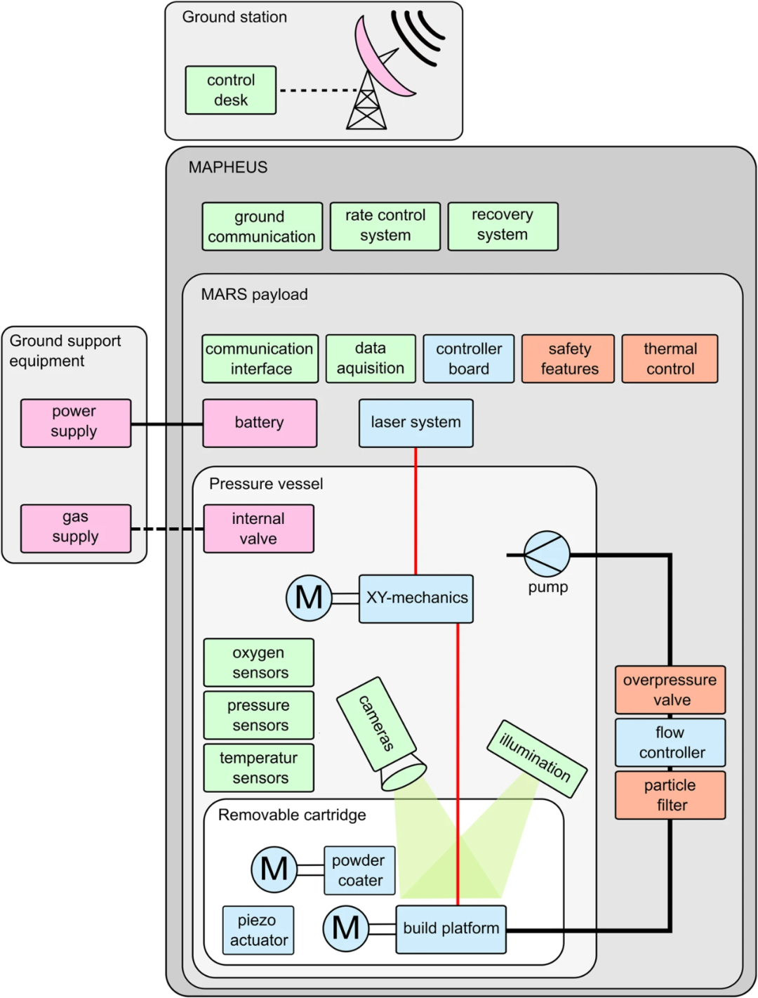
Fig. 3: System diagram of hardware and communications of MARS-M within MAPHEUS.
This diagram deconstructs the system into subgroups starting from the lowest level of the removable cartridge, up to the MAPHEUS payload support systems and vehicle.
Programming and Device Limitations
Building the above hardware and software is the first step to start manufacturing parts, and next, the manufacturing process must be adapted to the selected materials. The software and configuration depend solely on the equipment used for manufacturing parts, while the combination of laser power, scanning speed, layer thickness, and scanning strategy (sometimes including gas composition) depends on the selected powder. To adjust these parameters, the MARS-M device uses standard Smoothie-style G-code, and is also equipped with a set of device-specific M commands. The most commonly used G and M commands in MARS-M, along with their available parameters, effective variable ranges, and coding examples, are included in the firmware documentation (https://smoothieware.org/supported-g-codes, last accessed: February 28, 2023). Each parameter of the G commands is a string with a precision of four decimal places, while the small numeric strings of the M commands represent integer values. The code can be run from an internal storage card (required during flight), sent via Telnet connection from the ground station, or input as individual commands through a web interface.
When manufacturing with powders of different compositions, adjustments and optimizations of laser speed, scanning speed, fill spacing, and layer thickness are required. To generate G-code for manufacturing test specimens, we utilize software scripts to output code files (details in the next section). Additionally, to generate more complex three-dimensional geometries, powerful and recognized slicing software (such as open-source software Cura or Slic3r) can be used to process CAD models, generating G-code suitable for FFF-type printers, with appropriate setting adjustments for the device. Subsequently, LabVIEW software must be used to post-process the generated G-code, removing instructions and parameters specific to the FFF process while retaining geometric information, and adding instructions and parameters for laser processing, airflow control, and powder spreading G-code sequences, ensuring that no instructions exceed device limitations, such as the maximum travel range of the axes.
Results and Discussion
Flight Certification and Calibration Experiments
Before participating in the sounding rocket flight mission, the entire MARS-M payload was first mounted on the Novespace zero-gravity aircraft for parabolic flight microgravity testing, completing 62 parabolic flights over two flight days, each generating about 20 seconds of microgravity environment. To meet the safety requirements of parabolic flights, we made minor adjustments to the hardware, but this did not affect its functionality. During the parabolic flights, the powder handling mechanism and control algorithms were calibrated and adapted to weightlessness, but due to the short microgravity time, no laser melting operations were conducted. After each flight, the stacking condition of the powder layers was analyzed. The airflow settings proven suitable for microgravity environments during parabolic flights were similarly applied in laboratory experiments and the MAPHEUS sounding rocket flight mission. Using these settings, laying down a layer of powder took 15 seconds. The parabolic flight tests used 1.4404 stainless steel powder with a particle size of 20 – 53 microns, and zirconium-based metallic glass AMZ4 powder with a particle size of 45 – 100 microns (now industrial-grade AMLOY-Zr01, Heraeus AMLOY). After passing the parabolic flight tests, the device also successfully passed operational certification under vacuum conditions in environmental testing. In this configuration, the laser system successfully passed aerospace flight certification on the MAPHEUS sounding rocket.
The optimization of the manufacturing process was conducted on the ground, gradually expanding the size of manufactured parts: from lines (one-dimensional), thicker line segments with a thickness of 2 millimeters (1.5-dimensional, see Figure 4), to planes (two-dimensional) and solids (three-dimensional, with possibly different layers, see Supplementary Figures 2 and 3). Referencing relevant literature, we used different ranges of laser speeds (1000 – 5500 millimeters/minute) and laser powers (55 – 230 watts) for manufacturing. As shown in Figure 4, a two-dimensional line segment grid was created on the build platform, with laser power increasing in the Y-axis direction and laser scanning speed increasing in the X-axis direction.
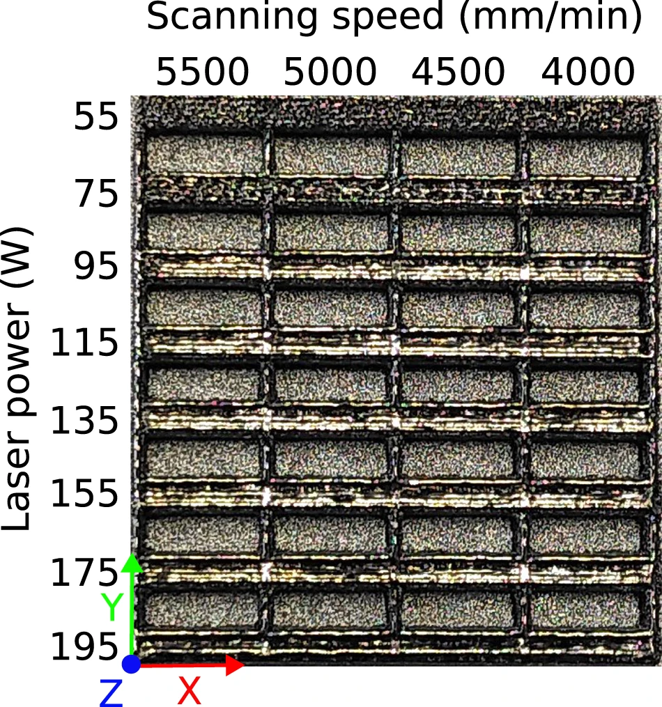
Fig. 4: Example of segments of AMZ4 with varying parameters.
In the early stages of the optimization process, we employed a wide range of laser powers and scanning speeds. Typically, the edges of the first test manufactured parts exhibited significant defects, which could be excluded in subsequent manufacturing: when energy input was too high (high power and low speed, see Figure 4 lower right), high porosity and spherodization occurred; while when energy input was insufficient (low power and high speed, see Figure 4 upper left), the surface was very rough, with clearly un-melted powder. In the latter case, the energy density might be too low, and although powder particles fused together, it was insufficient to weld them to the build platform. Supplementary Figure 1 shows multiple parameters and the additional effects brought about by their variations. By narrowing the parameter range for each new line segment, we were able to quickly find settings considered “optimal” within the device’s limitations: complete melting of the powder, minimal spherodization, lowest porosity, and the smoothest and glossiest surface. Additionally, for metallic glass materials, the proportion of crystalline phases should be as small as possible—ideally zero.
We first analyzed the quality of different manufacturing results through optical inspection (surface appearance). Once the parameter range was further narrowed, scanning electron microscopy (SEM, Zeiss Merlin) and X-ray diffraction (Bruker, D8Advance) were used to observe differences in microstructure: uniformity, smaller pore sizes, and proportions of crystalline phases. Using this method, we selected the “A + B” scanning strategy shown in Figure 5. This strategy includes two different layers A and B, which are almost identical but offset by half a fill spacing, and the laser scanning directions are opposite, with the laser moving along the axis perpendicular to the illustrated plane (Layer A: towards the observer, Layer B: away from the observer). It was found that this strategy reduces porosity and voids when manufacturing solid parts.
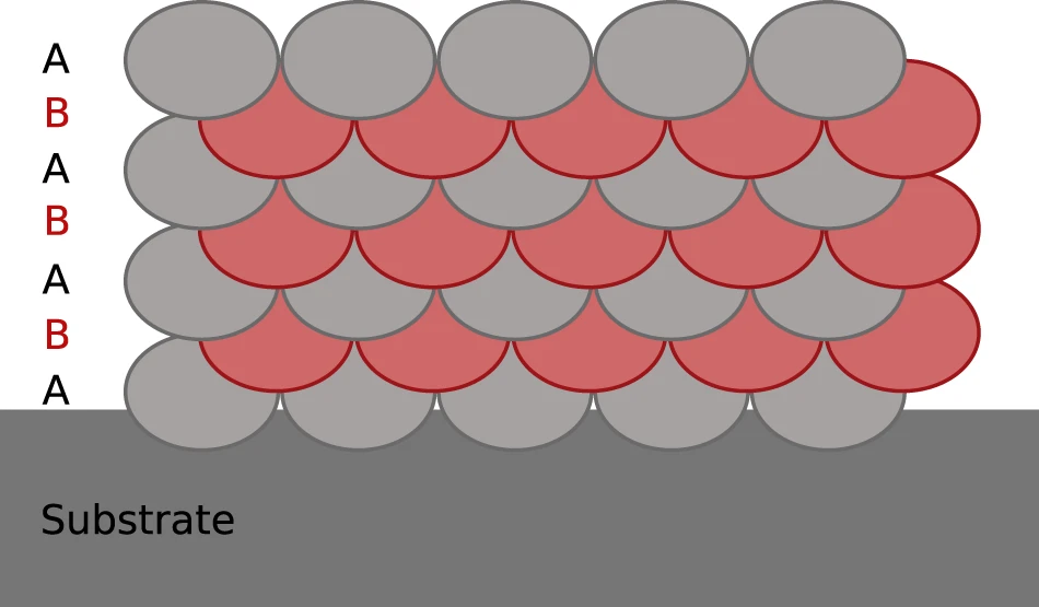
Schematic representation of the segments “A + B” scanning strategy.
For parts made from metallic glass materials, once their density reaches the expected standard, a more detailed inspection of the crystalline content is conducted. Different laser powers and scanning speeds yield different proportions of crystalline phases. Figure 6 shows the results of scanning electron microscopy (SEM, accelerating voltage 12 kV, using backscattered electron detection, working distance 12.2 mm) for parts formed using the “A + B” scanning strategy, with a laser power of 115 watts and a scanning speed of 5500 millimeters/minute, formed in 20 layers, each 100 microns thick. Although all line segment samples contain some crystalline phases, the selected part with a higher crystalline content in Figure 6 has enhanced contrast to observe microstructural differences more clearly. This part exhibits crystalline regions at the interlayer boundary (the dark areas in Figure 6). In the left image of Figure 6, these regions are periodically distributed; while in the right image, the distribution of crystalline regions appears more chaotic, but when compared with Figure 5, a pattern can be observed. Especially at the edges of the part, crystalline regions are notably located at the boundaries of each clad segment.
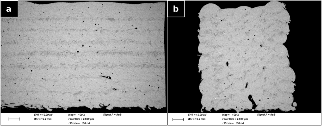
Fig. 6: SEM pictures.
We optimized parameters for various materials (AMZ4, Vit105, Ti6Al4V, and 316L stainless steel) using the above methods. For glassy materials, we selected laser powers and scanning speeds that produced the smallest proportions of crystalline phases. The parameters determined for AMZ4 in the laboratory (laser power 75 watts, scanning speed 4000 millimeters/minute) were subsequently used for part manufacturing in the rocket flight experiment (see Figure 7).
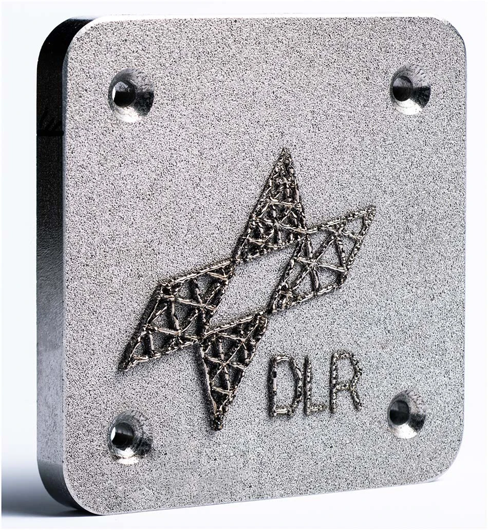
Fig. 7: Part built from eight layers from AMZ4 powder in microgravity.
Microstructural Characterization of Zirconium-Based Metallic Glass Manufactured with MARS-M
Since 2021, the MARS-M device has participated in space flight experiments mounted on MAPHEUS-11 in May 2021, MAPHEUS-10 in December 2021, and MAPHEUS-09 in January 2022. Each flight used AMZ4 powder with a particle size of 15 – 45 microns (industrial grade, Heraeus) as feedstock, with performance parameters detailed in Table 1. Next, we will analyze the flight experiment samples for the first time. In addition to the samples successfully manufactured in microgravity during the MAPHEUS-10 flight mission, we also prepared identical components under laboratory conditions. As shown in Figure 7, due to the limitation of microgravity time (i.e., 6.5 minutes), the thickness of the flight samples is limited, and they are easily damaged when removed from the build platform. Therefore, synchrotron measurements were conducted in transmission mode, with the beam perpendicular to the build platform, while reducing the platform thickness to about 500 microns to minimize signal interference from the steel and avoid damaging the flight samples.
Figure 8 shows partial comparison results between the flight sample (referred to as M10-µg, manufactured parameters of laser power 75 watts, scanning speed 4000 millimeters/minute) and the laboratory sample (M10-lab, with the same parameters), with two typical curves obtained from the diffraction spectra integration. The figure also displays the signal generated by the build platform for peak identification. It is evident that the steel used for the build platform generates a signal, and the samples exhibit some crystalline phenomena. The differences between M10-µg and M10-lab are minor, possibly due to slight differences in thickness, with M10-lab being two layers thicker than M10-µg (i.e., 200 microns).
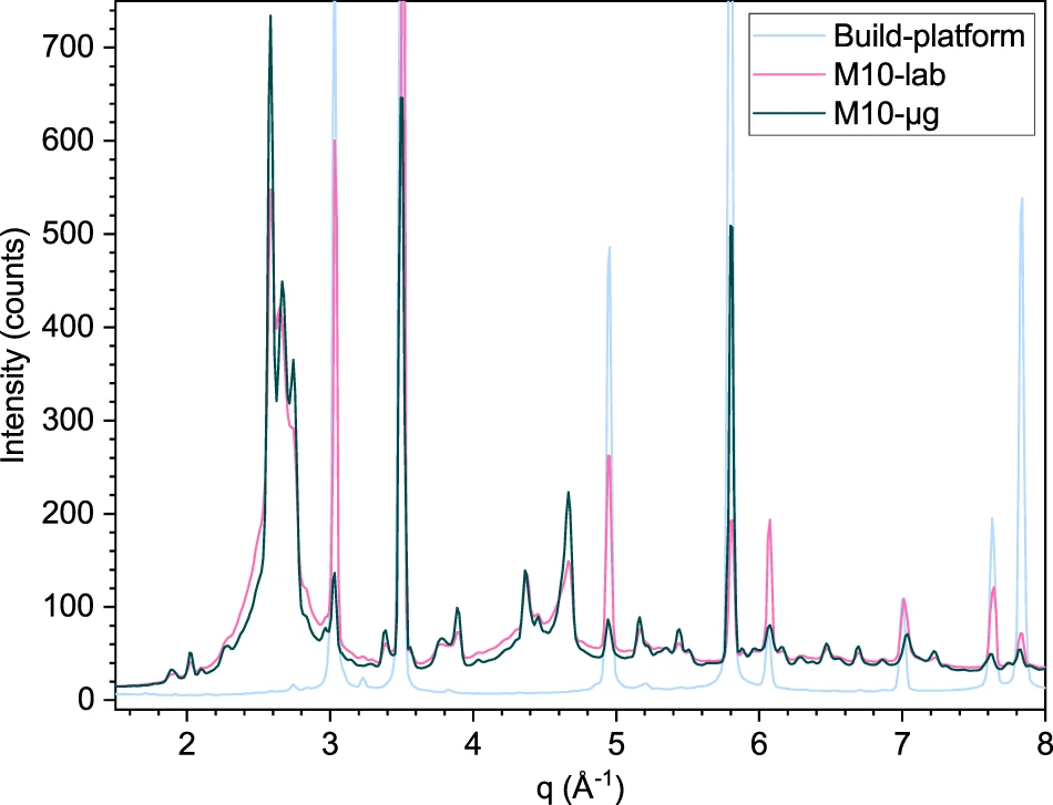
Fig. 8: M10-µg sample vs. M10-lab sample in synchrotron.
As mentioned above, MARS-M stabilizes powder in a microgravity environment by allowing gas to flow through the porous build platform. It can be imagined that airflow and porosity will affect melt flow dynamics and heat transfer, but the extent of this influence is currently unclear.
In summary, AMZ4 samples are not completely amorphous. For AMZ4, this can at least be partially explained by the fact that in industrial-grade laser-based powder bed fusion (PBF-LB) processes, scanning speeds are typically much faster than those achievable by MARS-M, which would result in a higher proportion of amorphous material in the final product. This is due to different design standards and optimization goals. In industrial production, speed is a highly weighted factor, while for rocket payloads, compactness and robustness are key. Nevertheless, multi-layer ground experiments indicate that most areas of the samples are amorphous. Crystalline regions are located at interlayer boundaries, which requires further investigation. To further improve the process, we are developing different forming strategies to reduce internal stress and testing different materials.
 However, metallic glass samples were successfully manufactured using AMZ4 powder on the sounding rocket. This demonstrates the effectiveness of the airflow-assisted powder handling concept in a microgravity environment. The next step is to conduct related processes on an orbital platform to obtain longer microgravity experiment times.Source: Yangtze River Delta G60 Laser AllianceSpecial ProcessingWeChat ID:china-ntmSpecial Processing Industry WeChat Public PlatformIf you find this article useful, please share and click “See”!