This article introduces the Proteus simulation system for a 5-wire 4-phase stepper motor driven by ULN2003. The system implements forward and reverse rotation, speed adjustment, and single-step testing functions through button control. It details the structural characteristics (5 leads/4 phase windings) and operating modes (single-phase, double-phase, eight-phase) of the 5-wire 4-phase stepper motor, as well as the features and circuit connection methods of the ULN2003 driver chip. A complete hardware setup guide is provided, including component selection (AT89C51, ULN2003, BUTTON, etc.) and circuit design diagrams, along with core control program code to achieve functions such as direction switching and speed adjustment. This simulation system is suitable for teaching demonstrations on stepper motor driving, providing a practical platform for beginners to understand motor control principles.
Demonstration Video
1. Function Description:
This simulation uses ULN2003 to drive a 5-wire 4-phase stepper motor, allowing control of the stepper motor’s forward rotation, reverse rotation, acceleration, deceleration, and single-step testing through button inputs.
2. Preparation Before Class:
1. Prepare a computer.2. Download and install Proteus 9.0 software. (For installation instructions, follow the WeChat public account at the bottom of this article and reply with 0005)3. Download and install Keil 5 C51 software. (For installation instructions, follow the WeChat public account at the bottom of this article and reply with 0007)PS: This tutorial uses Proteus 9.0 and KEIL 5 C51.
3. Start Building:
1. Select Components
Open the PROTEUS software, click the icon below 【P】, and sequentially select the components shown below: 【ULN2003】, 【AT89C51】, 【BUTTON】, 【CAP】, 【MOTOR-STEPPER】………
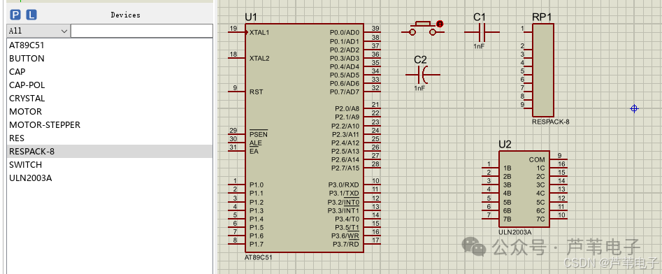
The above image shows the names and appearances of the components, which are the 51 microcontroller, capacitor, and resistor.
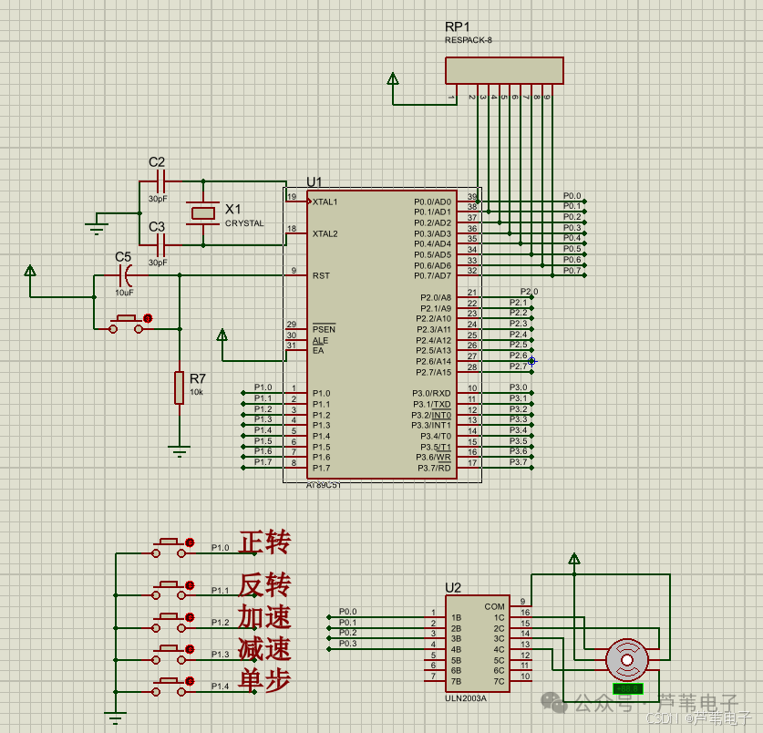
2. Build the Circuit
After a long time, it will eventually look like the image below:
3. Enter the World of Stepper Motors
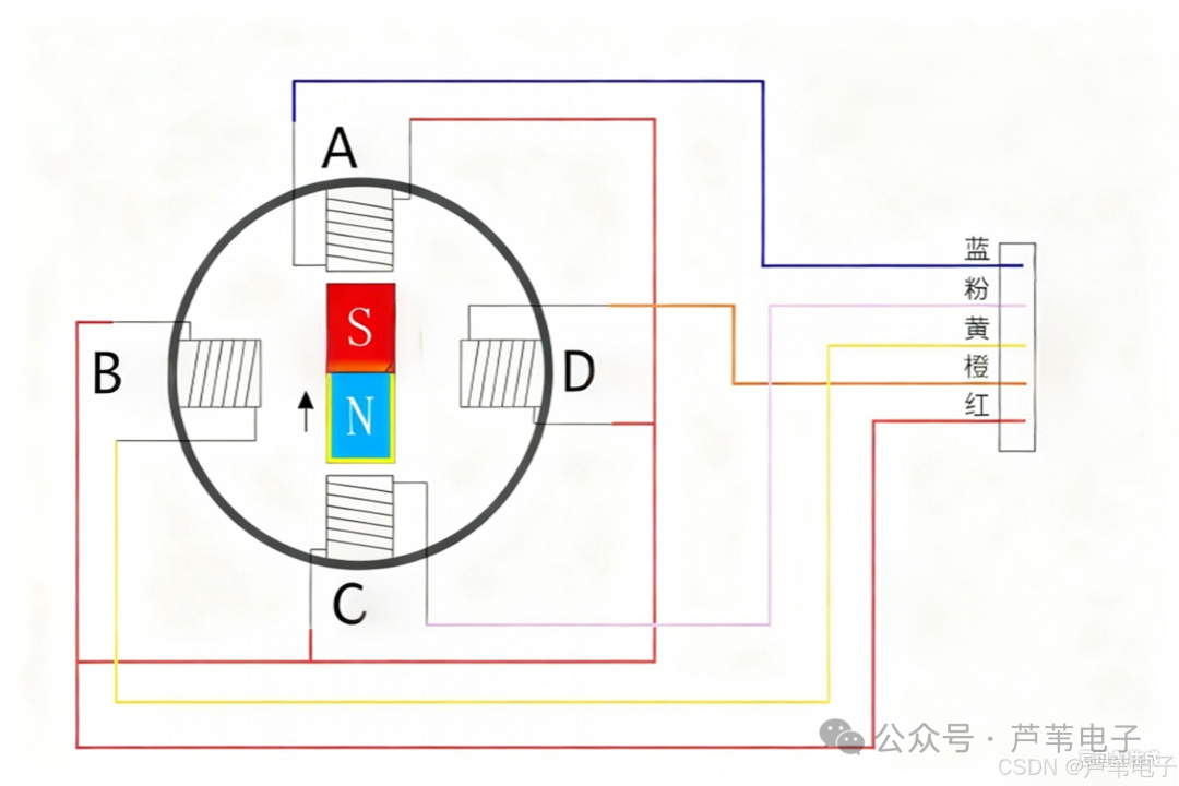
This simulation uses the “MOTOR-STEPPER” stepper motor, which generally represents a 5-wire 4-phase stepper motor. In the Proteus simulation, the two middle wires are both VCC. The 5-wire 4-phase stepper motor is a type of stepper motor that operates similarly to other stepper motors, relying on pulse signals for rotation. It is suitable for scenarios requiring high torque output, such as controlling the rotation of small robotic arm joints. Additionally, during simulation, it can be used with devices like the ULN2003A Darlington driver to achieve corresponding driving and control. The four phases of this stepper motor A, B, C, D are shown in the image below.

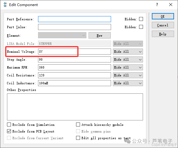
Set the motor voltage to 5V and the step angle to 90 degrees, meaning the A->B phase rotates 90 degrees.
3.1 Structural Details
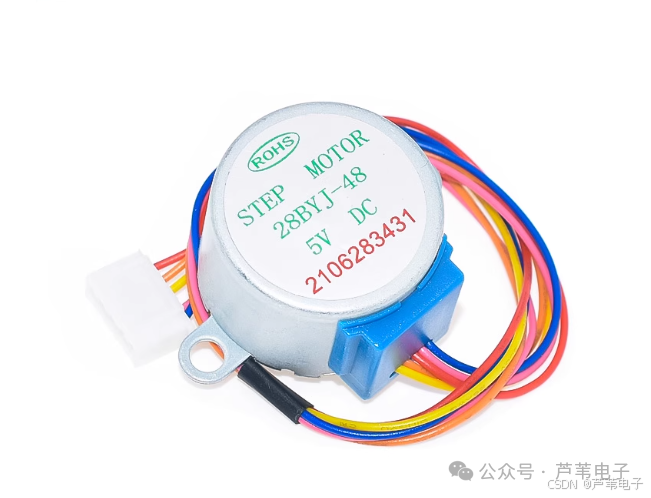
The “five wires” of the 5-wire 4-phase stepper motor refer to the five leads that the stepper motor has, including four phase wires and one 5V power supply wire; the “four phases” indicate that the stepper motor has four phase stator windings, which are four coils (windings). If the two coils’ center taps are not connected, it becomes a 4-phase 6-wire motor; if there are no center taps, it becomes a 2-phase 4-wire motor. Its operation is based on the principle of electromagnetism, allowing the coils to generate magnetic fields that cause rotation through the magnetic force of the center magnet.
The physical image of the 5-wire 4-phase stepper motor is shown below, powered by 5V.
3.2 Operating Mode Details
Single-step (Single-phase working mode) In this mode, only one coil is energized at a time, causing the stepper motor to rotate by changing the energized coil. For the 5-wire 4-phase stepper motor, assuming its four coils are called A, B, C, D, the energizing sequence in single-step mode is: A, B, C, D. However, it should be noted that since the 5-wire 4-phase stepper motor cannot conduct reverse current, these are the only energizing conditions.
Double-step (Double-phase working mode) In this working mode, two coils are energized at a time, and the stepper motor rotates by changing the energized coils. The energizing sequence for the 5-wire 4-phase stepper motor in double-step mode is: AB, BC, CD, DA.
Single and Double-step (Eight-phase working mode) The single and double-step working mode alternates between single-step and double-step modes. When the 5-wire 4-phase stepper motor operates in eight-phase mode, the energizing sequence is: A, AB, B, BC, C, CD, D, DA.
3.3 Other Important Details
The stepper motor must be driven to operate, and the driving signal must be a pulse signal. Without pulses, the stepper motor remains stationary; when appropriate pulse signals are applied, it will rotate at a certain angle (called the step angle), and the rotation speed is proportional to the pulse frequency. The coils are inductive and have frequency characteristics; different motors have different frequencies. If DC voltage is directly applied to the coils, they will heat up, while pulses can generate force without excessive heat. However, the rich frequency components of the pulse spectrum can cause the motor to heat up and vibrate due to unnecessary frequencies. In this case, sine waves can replace pulses, which is a subdivision technique to solve this problem. Additionally, after the stepper motor stops, all four phase pins must be set to high level; otherwise, the stepper motor will heat up because the common terminal is at high level. If all pins are at high level, no current will flow, preventing overheating.
In summary, understanding these structural and operational details of the 5-wire 4-phase stepper motor will enable us to use and control it better. In practical operations, it is essential to choose the appropriate working mode based on specific needs and pay attention to the driving signal and pin states when stopping.
4. Understanding UNL2003
ULN2003 device function explained in detail, a boon for beginners!
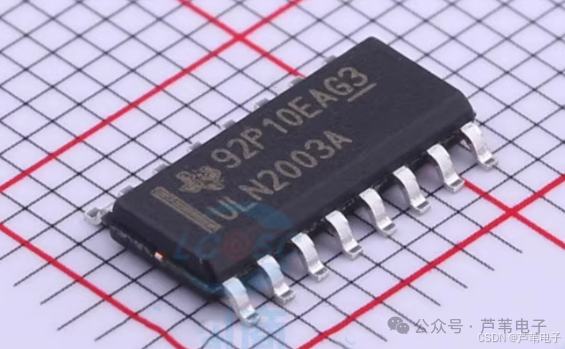
1. Basic Information of the DeviceULN2003 is a high-voltage, high-current composite transistor array consisting of seven silicon NPN composite transistors, typically packaged in DIP – 16 or SOP – 16 plastic. It acts like a diligent little assistant, playing an important role in the electronic world.
2. Main Features Easy to connect: Each Darlington pair is connected in series with a 2.7K base resistor, allowing it to connect directly with TTL and CMOS circuits at a 5V operating voltage, handling data that previously required standard logic buffers. It’s like having a universal interface that can easily connect with many different circuits. High voltage and current: It can handle high operating voltages and currents, with a sink current of up to 500mA, and can withstand 50V when off, allowing outputs to run in parallel under high load currents. Imagine it as a strong heavyweight champion, capable of withstanding significant pressure and current. Strong compatibility: Input is compatible with various logic types, such as TTL and CMOS, making it easy to connect with other logic circuits. No matter what type of circuit it collaborates with, it can integrate well. Built-in protection: Each Darlington pair has a cathode clamp diode to protect the circuit from reverse voltage spikes generated during inductive load switching. It’s like putting a protective coat on the circuit, making it safer.
3. Pin Functions
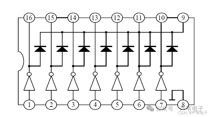
Input pins (pins 1 – 7): These are the CPU pulse input terminals, with each port corresponding to a signal output. They act like the “ears” of the circuit, receiving pulse signals from the CPU. Ground pin (pin 8): Used for inductive loads, this pin connects to the positive terminal of the load power supply to achieve continuous flow. If this pin is grounded, it effectively connects the collector of the Darlington transistor to ground. You can think of it as the “foundation” of the circuit, ensuring stable operation. Output pins (pins 10 – 16): These are the pulse signal output terminals, corresponding to the respective input pin signals. They act like the “mouth” of the circuit, outputting the processed signals.
4. Operating Principle ULN2003 is also a 7-channel inverter circuit, meaning when the input is high, the output is low; when the input is low, the output is high. It is used to amplify current and increase driving capability. For example, a microcontroller output pin typically outputs only a few mA, which is insufficient to drive motors, relays, or solenoids. However, with ULN2003 amplification, these devices can be directly controlled through the microcontroller’s output pin.
5. Application Scenarios ULN2003 is commonly used in control circuits for microcontrollers, smart instruments, PLCs, and digital output cards, and can directly drive loads such as relays. It’s like a multifunctional tool that can be found in many different electronic devices.
5. Program Design:
Follow the WeChat public account below to obtain free materials.
1. Key Scan Program
In the key scan subroutine, control the motor’s direction and speed, as well as single-step testing.
/*****************************************************************
* Function: // Key scan subroutine
*****************************************************************/
void key_scan(void)
{
    if(key1 == 0)
    {
        Delay_xms(10);
        if(key1 == 0)
        {
            motor_flag_new=0; // Clockwise rotation
        }
    }

    if(key2 == 0)
    {
        Delay_xms(10);
        if(key2 == 0)
        {
            motor_flag_new=1; // Counterclockwise rotation
        }
    }

    if(key3 == 0) // Acceleration
    {
        Delay_xms(10);
        if(key3 == 0)
        {
            motor_speed-=20;
            if(motor_speed<=20)
            {
                motor_speed=20;
            }
        }
    }

    if(key4 == 0) // Deceleration
    {
        Delay_xms(10);
        if(key4 == 0)
        {
            motor_speed+=20;
            if(motor_speed>=1000)
            {
                motor_speed=1000;
            }
        }
    }
    if(key5 == 0) // Single-step operation
    {
        Delay_xms(10);
        if(key5 == 0)
        {
            motor_flag_new=2;
        }
    }
}
2. Main Program
/*****************************************************************
* Function: // Main function
*****************************************************************/
void main(void)
{

    uchar step_num =0;
        MotorData=0x0;
        Delay_xms(50); // Wait for system stabilization
        while(1)
        {

            key_scan();
            if(motor_flag_new != motor_flag_old) // Stop rotation when switching directions
            {
                motor_flag_old=motor_flag_new;
                MotorData=phaseccw[step_num]; // Stop rotation
                Delay_xms(100);
            }
            if(motor_flag_old == 0) // Clockwise rotation
            {
                step_num=step_num+1;
                if(step_num>=8)
                {
                    step_num=0;
                }
                MotorData=phaseccw[step_num];
                Delay_xms(motor_speed);
            }
            if (motor_flag_old == 1) // Counterclockwise rotation
            {

                step_num=step_num-1;
                if(step_num>=8)
                {
                    step_num=7;
                }
                MotorData=phaseccw[step_num];
                Delay_xms(motor_speed);

            }
            if(motor_flag_old == 2) // Single-step testing
            {
                step_num=step_num+1;
                if(step_num>=8)
                {
                    step_num=0;
                }
                MotorData=phaseccw[step_num];
                motor_flag_old=3;
                motor_flag_new=3;
            }


        }
}
6. Free Material Acquisition:
Follow the WeChat public account below,
Reply in the public account with
021
After replying, the material will be automatically sent.