Detailed Introduction to Modbus Communication and Example Programming for Siemens S7-200 SMART
(By Engineer He from JuControl)
Overview: Both parties in communication must support one of the modes mentioned above. Modbus is a master/slave communication mode with a single master. There can only be one master on a Modbus network, and the master does not have an address. The address range for slaves is 0 – 247, where 0 is the broadcast address, and the actual address range for slaves is 1 – 247. The Modbus communication standard protocol can be transmitted through various transmission methods such as RS232C, RS485, fiber optics, and radio. The S7-200 CPU implements RS485 half-duplex communication using the free port function of the S7-200 SMART. For detailed protocols and specifications, please visit the Modbus organization’s website or message me:
1. Siemens S7-200 SMART as Modbus Slave
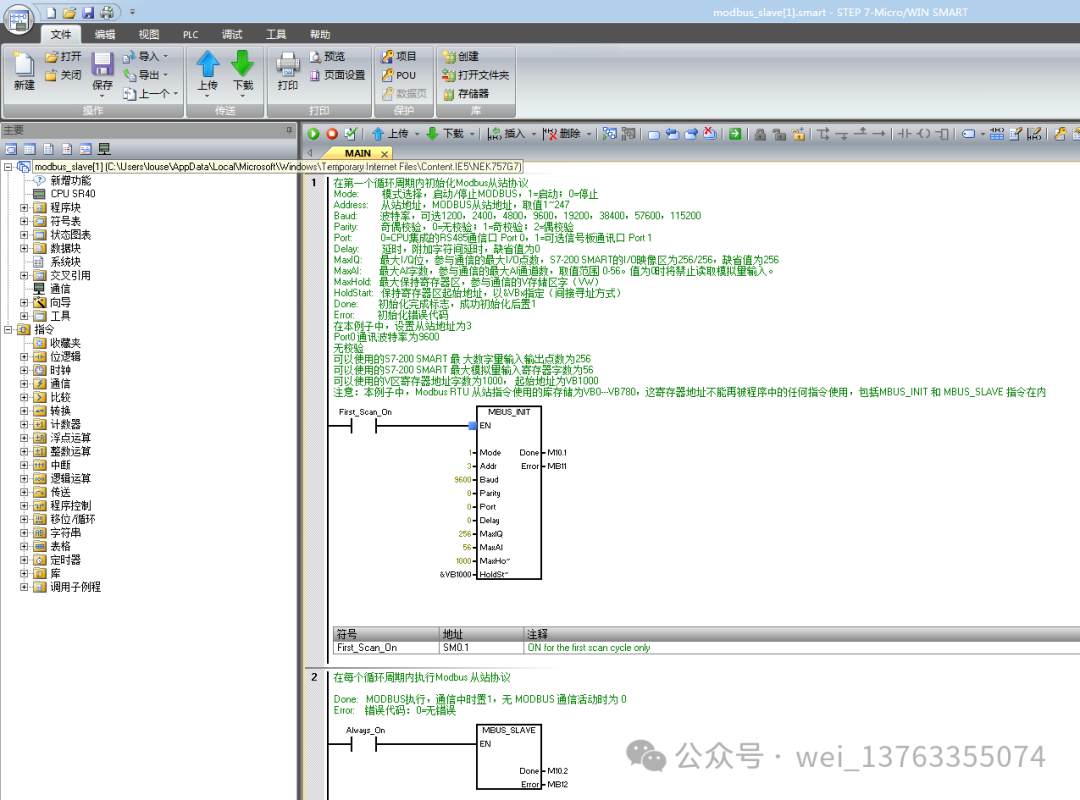
1. Check the Micro/WIN SMART Modbus RTU Slave Instruction Library (Figure 1), which should include the MBUS_INIT and MBUS_SLAVE subprograms.Figure 1. Library instructions in the instruction tree
2. During programming, use SM0.1 to call the subprogram MBUS_INIT for initialization, and use SM0.0 to call MBUS_SLAVE, specifying the corresponding parameters. Detailed explanations of the parameters can be found in the local variable table of the subprogram;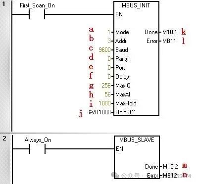 Figure 2. Calling Modbus RTU communication instruction library The parameters in the figure are as follows:
a.Mode selection: Start/Stop Modbus, 1=Start; 0=Stop
b.Slave address: Modbus slave address, value range 1~247
c. Baud rate: Options are 1200, 2400, 4800, 9600, 19200, 38400, 57600, 115200
d. Parity: 0=No parity; 1=Odd parity; 2=Even parity
e. Port: 0=Integrated RS-485 in CPU, 1=RS-485 or RS-232 on optional signal board.
f. Delay: Additional delay between characters, default value is 0
g. Maximum I/Q bits: Maximum number of I/O points participating in communication, the I/O image area of S7-200 SMART is 256/256 (currently can only connect a maximum of 4 expansion modules, so the maximum I/O points are 188/188)
h. Maximum AI words: Maximum number of AI channels participating in communication, up to 56
i. Maximum holding register area: Participating communication V storage area words (VW)
j. Starting address of holding register area: Specified by &VBx (indirect addressing method)
k. Initialization complete flag: Set to 1 after successful initialization
l. Initialization error code
m. Modbus execution: Set to 1 during communication, 0 when there is no Modbus communication activity.
n. Error code: 0=No error
3. Allocate library instruction data area (Library Memory) in the CPU’s V data area The Modbus Slave instruction library requires a global V storage area of 781 bytes. Calling the STEP 7 – Micro/WIN SMART Instruction Library (instruction library) requires allocating a library instruction data area (Library Memory). The library instruction data area is the variable storage space needed by the corresponding library’s subprograms and interrupt programs. If the library instruction data area is not allocated during programming, many identical errors will occur during compilation.
Operation steps:
1) In the instruction tree’s Project, right-click on Program Block, and select Library Memory from the pop-up shortcut menu. As shown in Figure 3: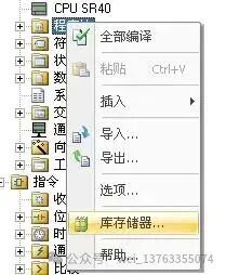
1. If necessary, use the master station software for testing.
Note: The holding register area specified by the subprogram parameters HoldStart and MaxHold is allocated in the V data storage area of the S7-200 SMART CPU, and this data area must not overlap with the library instruction data area; otherwise, errors will occur during runtime, and communication will not function properly. Note that the holding register area in Modbus is addressed by “words”, meaning MaxHold specifies the number of VW, not VB. In the example in Figure 2, the Modbus holding register area starts from VB1000 (HoldStart = VB1000), and the holding register is 1000 words (MaxHold=1000). Since the holding register is in words (two bytes), this communication buffer actually occupies VB1000 to VB2999, totaling 2000 bytes. Therefore, when allocating the library instruction reserved data area, at least avoid the range of VB1000 to VB2999.
Note: Be aware of the size of the V storage area of the CPU you are using! The size of the V data storage area varies by CPU model. The size of the Modbus holding register area should be selected according to your needs.
After compiling the project containing the Modbus RTU Slave instruction library and downloading it to the CPU, running some Modbus testing software on the programming computer (PG/PC) can verify whether the S7-200 SMART CPU’s Modbus RTU communication is functioning correctly, which is useful for troubleshooting. The testing software connects to the CPU via the computer’s serial port (RS-232) and PC/PPI cable. If necessary, the PC/PPI cable must be set to the free port communication mode. You can find similar software on some download websites or message me, such as ModScan32, etc.
Modbus RTU Slave address corresponds to the S7-200 SMART address: Modbus addresses always appear in the form of 00001, 30004, etc. The correspondence between the internal data storage area of the S7-200 SMART CPU and the four types of Modbus addresses 0, 1, 3, and 4 is as follows:
Table 1. Modbus Address Correspondence Table
|
Modbus Address |
S7-200 SMART Data Area |
|
00001 ~ 00256 |
Q0.0 ~ Q31.7 |
|
10001 ~ 10256 |
I0.0 ~ I31.7 |
|
30001 ~ 30056 |
AIW0 ~ AIW110 |
|
40001 ~ 4xxxx |
T ~ T + 2 * (xxxx -1) |
Where T is the starting address of the buffer in the S7-200 SMART CPU, i.e., HoldStart.
If the address in the V storage area of the S7-200 SMART CPU is known, the formula for calculating the Modbus address is as follows:
Modbus Address = 40000 + (T/2+1); T is even
Modbus RTU Slave Instruction Library Supported Modbus Function Codes
The Modbus RTU Slave Instruction Library supports specific Modbus functions. The master station using this instruction library must comply with the requirements of this instruction library.
Table 2. Modbus RTU Slave Function Codes
|
Function Code |
Effect of the corresponding function code used by the master station on this slave |
|
1 |
Read the status of a single/multiple coils (discrete output points). Function 1 returns the ON/OFF status of any number of output points (Q). |
|
2 |
Read the status of a single/multiple contacts (discrete input points). Function 2 returns the ON/OFF status of any number of input points (I). |
|
3 |
Read a single/multiple holding registers. Function 3 returns the contents of the V storage area. In the Modbus protocol, holding registers are all “word” values, and up to 120 words of data can be read in a single request. |
|
4 |
Read a single/multiple input registers. Function 4 returns the analog data values of the S7-200 SMART CPU. |
|
5 |
Write a single coil (discrete output point). Function 5 is used to set a discrete output point to a specified value. This point is not forced; the user program can override the value written by the Modbus communication request. |
|
6 |
Write a single holding register. Function 6 writes a value to the holding register in the V storage area of the S7-200 SMART. |
|
15 |
Write multiple coils (discrete output points). Function 15 writes the values of multiple discrete output points to the output image register (Q area) of the S7-200 SMART CPU. The address of the output points must start at a byte boundary (e.g., Q0.0 or Q2.0), and the number of output points must be a multiple of 8. This is a limitation of this Modbus RTU Slave instruction library. These points are not forced; the user program can override the values written by the Modbus communication request. |
|
16 |
Write multiple holding registers. Function 16 writes multiple values to the holding registers in the V storage area of the S7-200 SMART CPU. Up to 120 words of data can be written in a single request. |
2. Modbus RTU Slave Routine
3. Conclusion
Thank you all for your support. In the next article, I will share a detailed introduction to Modbus master communication for Siemens SMART 200. If you need to learn about Siemens PLC programming software and learning videos (S7-300, S7-200), please forward + follow, message me or check my personal profile, where you can find “扣,扣”.