When the PLC output type is transistor type, it has a high-speed pulse output function. There are two forms of high-speed pulse output: one is Pulse Width Modulation, abbreviated as PWM; the other is Motion Control Output, abbreviated as PTO. This article introduces how to write PWM programs for the Siemens 200SMART ST30 PLC.
PWM output generates a pulse output with a fixed period and varying duty cycle, which can specify its period and pulse width in microseconds or milliseconds;
Period: 10 microseconds to 65535 microseconds or 2 milliseconds to 65535 milliseconds.
Pulse Width: 0 microseconds to 65535 microseconds or 0 milliseconds to 65535 milliseconds.
Duty Cycle: the ratio of pulse width to pulse period..
The steps to write a PWM program using the PLS instruction are as follows:
1) Select the pulse output point, which can be Q0.0, Q0.1, or Q0.3, and choose the output type.
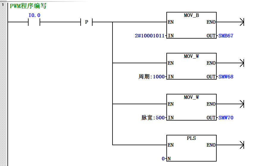
2) Modify the control byte of the corresponding output point (MOV_B).
3) Set the corresponding period value and pulse width (MOV_W).
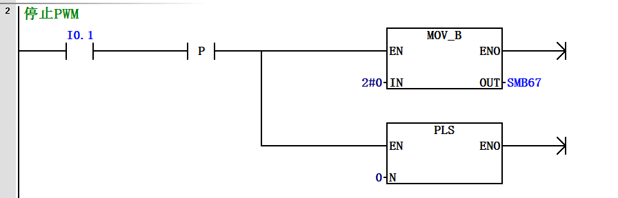
4) Use the pulse output instruction (PLS) to execute the pulse output.
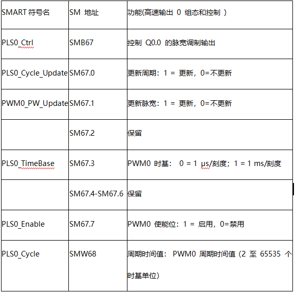
The control byte, period, and pulse width definitions for Q0.0 PWM output are shown in the table below:
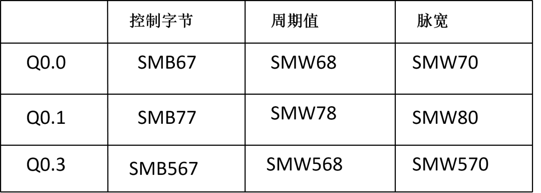
Q0.1, Q0.3, and Q0.0 are similar, just with different addresses; see the table below for addresses:
For example: Press the start signal connected to the input point I0.0, and Q0.0 will perform PWM output with a period of 1000MS and a duty cycle of 50%. Press the stop signal connected to the input point I0.1 to stop the output. The program is written as follows: