In previous issues, we detailed industrial control devices and control systems, as well as the communication protocols between systems and devices. Today, we will take a closer look at how industrial control systems are networked and the various forms of networking they can take. In future articles, we will analyze the networking logic of industrial control systems in different industries based on industry characteristics and process flows.Before we begin, let’s look at a diagram: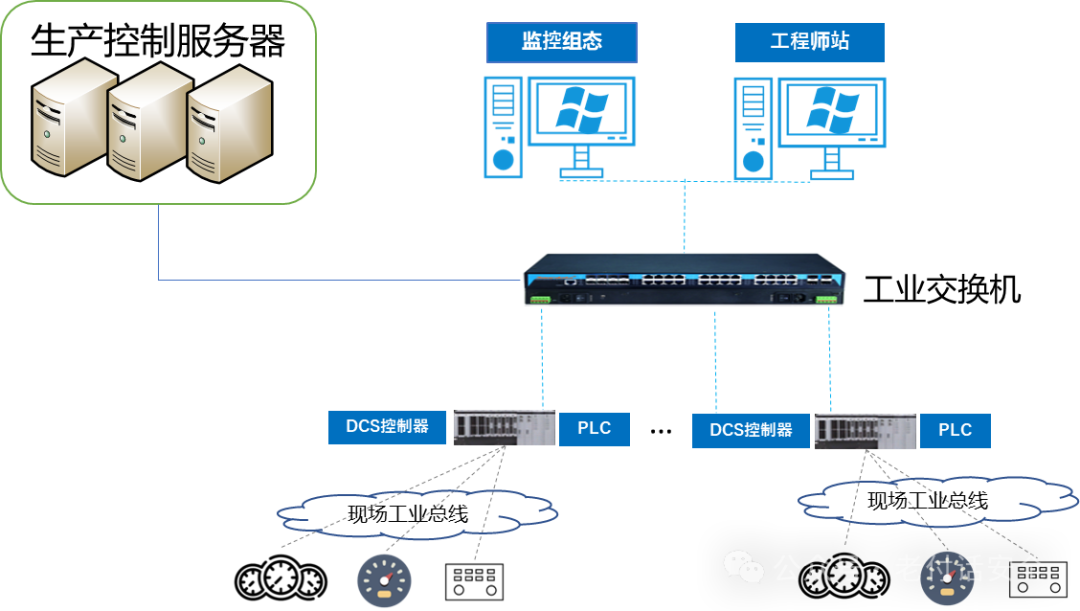 The basic networking of industrial control systems typically involves connecting the industrial host using Ethernet or fiber optics through an industrial switch to a PLC controller, with the PLC’s I/O cards connected to instruments and valves via fieldbus. Some upper-level application system servers (production management servers) are also connected through network switches.Here, we will understand the differences between industrial Ethernet switches and regular Ethernet switches:
| Comparison Dimension | 🔩 Industrial Ethernet Switch | 💻 Standard Commercial/Office Ethernet Switch |
|---|---|---|
| Design and Environmental Adaptability | • Wide Temperature Design:-40℃ ~ 85℃• High Protection Level:IP30~IP67, dustproof, waterproof, moisture-proof• Fanless, Rugged Housing(Metal):vibration-resistant, shock-resistant• DIN Rail/Panel Mounting | • Standard Temperature:0℃ ~ 40℃• Low Protection Level:usually IP20, placed in server rooms/weak current boxes• Plastic Housing, Fan Cooling• Rack-mounted/Desktop Installation |
| Power Supply and Reliability | • Redundant Power Input (24VDC/110VAC/220VAC)• Supports Power Failure Protection• High MTBF(Mean Time Between Failures)• Intrinsic Safety(suitable for explosion-proof environments) | • Single Power Supply(110VAC/220VAC)• No Redundant Power Design• Relatively Low MTBF• Not Suitable for Harsh Industrial Environments |
| Network Functions and Real-time Performance | • Supports Industrial Protocols:PROFINET, EtherNet/IP, Modbus TCP, etc., prioritizing industrial protocols in queue delays to ensure low latency.• High Precision Time Synchronization(IEEE 1588, PTP)• Redundant Protocols:PRP/HSR, ring redundancy (self-healing time <50ms)• Multicast Management(IGMP Snooping) optimization | • Standard Ethernet Protocol(TCP/IP)• Standard Network Synchronization(NTP), low precision• Supports STP/RSTP(convergence time from seconds to minutes)• Basic Multicast Management |
| Management and Maintenance | • CLI, Web Interface, Dedicated Network Management Software• Rich Status Indicators, facilitating quick diagnostics• Compatible with Network Management Tools | • Plug and Play(non-managed) orSimple Management(managed)• Simple Status Indicators• Standard SNMP Protocolfor management |
PLC System Architecture Diagram
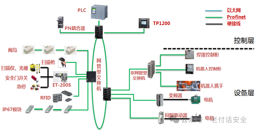
There are many ways to network PLCs and field devices. In this diagram, the PLC and device layer use Profinet for networking, while the field still uses Ethernet, but the running protocol is Profinet, combining the advantages of Ethernet.
The upper layer of the PLC connects the operator station and engineer station using Ethernet TCP protocol. In many small control system networks, the operator and engineer stations are combined into one, serving both monitoring and engineering modification functions, controlled by different permissions. Like this:
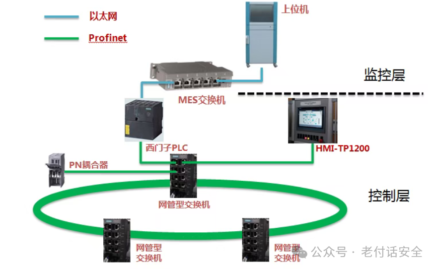
Currently, most scenarios are basically networked in a ring topology, although you may also encounter star topologies or bus topologies, all aimed at increasing reliability.
DCS System Architecture Diagram
Distributed Control System (DCS): A decentralized control system composed of process control and process monitoring levels, linked by a communication network, integrating the four C technologies: Computer, Communication, Display (CRT), and Control. Its basic design concept is decentralized control, centralized operation, hierarchical management, flexible configuration, and convenient setup. The system consists mainly of field control stations (I/O stations), data communication systems, human-machine interface units, operator stations, engineer stations, data acquisition stations, cabinets, power supplies, etc. The system has an open architecture that can provide multi-layer open data interfaces.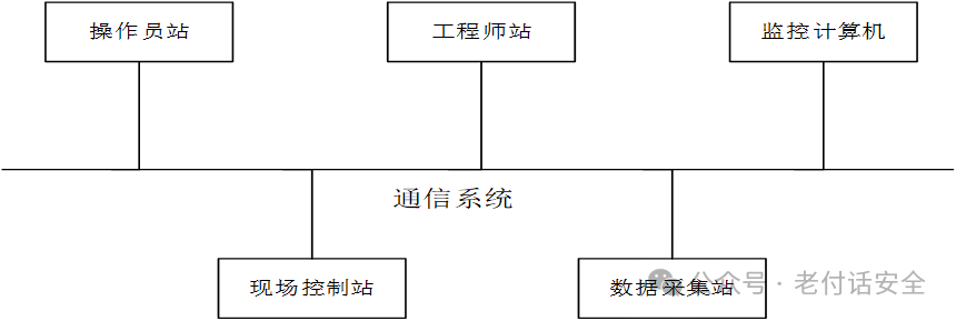 Below is the DCS system architecture diagram:
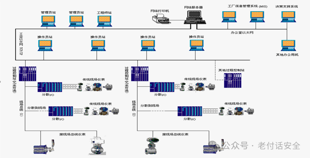
DCS systems are widely used in process manufacturing enterprises. To ensure reliability and continuity, networking generally adopts A/B network redundancy. Among all control system networks, DCS system networking requirements are high, and the networking is relatively complex.
SCADA System Architecture Diagram
Data Acquisition and Monitoring Control System (SCADA) main components: monitoring computer, Remote Terminal Unit (RTU), Programmable Logic Controller (PLC), communication infrastructure, Human-Machine Interface (HMI);
RTU (Remote Terminal Unit) is responsible for monitoring and controlling field signals and industrial equipment. This includes: digital input units, digital output units, analog input units, analog output units, pulse input units, pulse output units, and digital input units. It has telemetry, remote signaling, remote adjustment, and remote control functions.
SCADA has a wide range of applications, including power, metallurgy, security, water conservancy, sewage treatment, oil and gas, chemical, transportation, pharmaceuticals, and large-scale manufacturing for data acquisition, monitoring control, and process control.
The topology structure of SCADA systems is as follows:
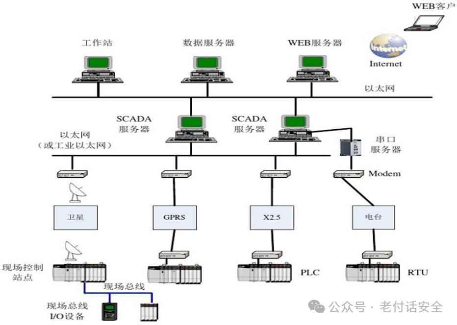
SCADA system networking is relatively simple, mainly focused on data acquisition and monitoring, but it also involves some simple control, such as valve opening and closing adjustments or digital signal adjustments.
The above outlines the networking structures of the three major industrial systems for reference. In the next issue, we will conduct a detailed analysis of ICS system topology networking according to industry attributes and industrial processes to facilitate the establishment of future industrial control security measures. Finally, let’s summarize the differences among the three major systems:
|
|
SCADA System |
DCS System |
PLC System |
|
Main Features |
Concentrates the strong field measurement and control capabilities of the PLC system and the strong networking communication capabilities of the DCS system, offering high cost-performance, suitable for scenarios where measurement and control points are extremely dispersed and control requirements are not very high. |
Suitable for industrial sites with many measurement and control points, high measurement and control accuracy, and fast measurement and control speed, featuring decentralized control and centralized monitoring, strong networking communication capabilities, reliable operation, easy expansion, convenient configuration, and simple operation and maintenance, but the system is expensive. |
Suitable for measurement and control in industrial sites, with strong field measurement and control capabilities, stable performance, high reliability, mature, widely used, and reasonably priced. PLCs often serve as the lower-level machines of SCADA systems. |
|
Geographical Scope |
Highly dispersed geographical locations |
Concentrated geographical locations (such as factories or areas centered around factories) |
Concentrated geographical locations |
|
Application Fields |
Remote monitoring industries (such as oil and gas pipelines, power grids, rail transportation systems including railway and urban rail transit systems) |
Process control industries (such as power generation, refining, food, and chemicals) |
Industrial automation (such as production lines) |

The end

@Please grant me strength, following and sharing is the greatest support@
+VX:TCMAFNS119 Join the group for discussion