In S7-200 SMART PLC programming, many beginners fall into the dilemma of “functionality achieved but program bloated”—when faced with requirements like “controlling the corresponding number of output bits based on stored values,” they tend to stack logic with numerous comparison instructions, making debugging cumbersome and subsequent modifications inflexible. This article starts from a real case of a student’s request for help, detailing how to use the FOR loop instruction combined with the SHBR shift register instruction to achieve lightweight program optimization, balancing practicality and scalability.
1. On-Site Pain Point: The “Inefficient Dilemma” of Stacked Comparison Instructions
Recently, I received a call for help from a student, whose problem was quite representative: the S7-200 SMART device he was responsible for needed to implement control logic of “memory value = number of output bits”—for example, if the value of VW0 in memory is 10, it should trigger 10 output actions; if the value is 25, it should trigger 25 output bits.
This student’s initial solution was to use comparison instructions: writing independent comparison logic for each possible value (from 1 to the maximum required value), triggering the corresponding number of output bits through set instructions when VW0 equals a certain value. However, this approach has obvious flaws: on one hand, if the maximum required output bits reach 30, 30 sets of similar comparison-set programs need to be written, leading to code redundancy and a high chance of errors; on the other hand, if the output bit range needs to be adjusted later, each comparison instruction’s parameters must be modified one by one, resulting in poor flexibility.
Essentially, the core of this problem is “transforming values into batch control of continuous output bits,” while the “point-to-point” control logic of comparison instructions clearly does not match this “batch requirement.” So, is there a more efficient programming approach?
2. Optimization Idea: Logical Shift from “Decoding” to “Shifting”
In response to the requirement, the initial reaction was to use the PLC’s decoding instruction (such as SEG). However, upon closer examination, it was found that the core function of the decoding instruction is “to trigger a corresponding single output bit based on the input value” (for example, input 3 triggers the third output bit), which cannot achieve the continuous multi-bit triggering requirement of “input value = number of output bits,” thus making the decoding instruction unsuitable.
Since continuous multiple output bits need to be triggered sequentially, the shift register instruction (SHBR) came into view. The core of the SHBR instruction is to control data to shift bit by bit in the register through “shift pulses,” which can perfectly achieve continuous activation of output bits; the number of shifts can be determined by the value in memory (VW0). At this point, when paired with the FOR loop instruction, the number of iterations can precisely control the execution times of the SHBR instruction, perfectly matching the control logic of “value = number of output bits”—this combination idea of “loop-controlled shifting” avoids instruction stacking while flexibly adapting to different output quantity requirements.
The specific logical chain can be summarized as: Get the target number of output bits from VW0 → Set the number of shifts through the FOR loop → Trigger the SHBR instruction in a loop to achieve continuous activation of output bits → Finally form the corresponding number of “1” states in the output register.
3. Program Implementation: Practical Writing Based on 32 Output Bits
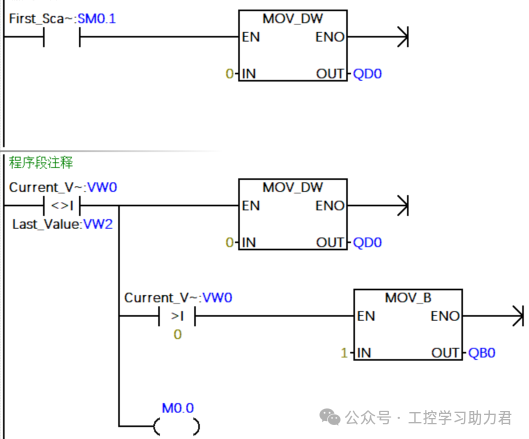
After clarifying the idea, we wrote a test program based on the 32 output bits of the S7-200 SMART (corresponding to a double word QD0). The 32 bits are the default length of double word registers in S7-200 SMART, covering most output needs of small to medium-sized devices, making the program highly versatile.
1. Variable Definition: Clarifying Core Control Parameters
First, define key parameters in the variable table to ensure clear logical associations:
-
VW0: Target output bit count register, storing the number of output bits to be activated (e.g., 5, 10, 25, etc.), set by external signals or human-machine interface.
-
QD0: Output control register, corresponding to 32 output bits from PLC’s Q0.0-Q3.7, where the “1” state in the register corresponds to output actions.
-
VW2: Auxiliary variable for loop counting, used to control the number of iterations in the FOR loop, consistent with the value of VW0.
-
I0.0: Program start trigger signal, rising edge triggers the execution of the entire control logic.
2. Core Program: Combination Application of FOR Loop and SHBR
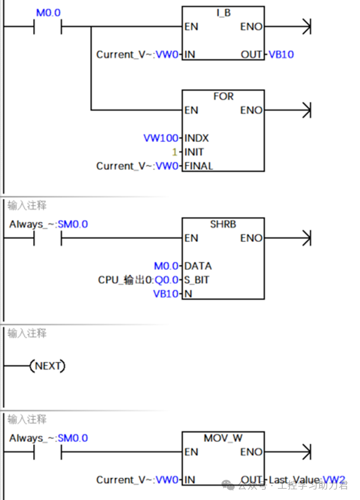
The main program is divided into three stages: “Initialization → Loop Shifting → Result Output,” with the core code as follows (in line with the instruction format of S7-200 SMART programming software):
-
Initialization Stage: When I0.0 triggers a rising edge, first clear QD0 (to avoid interference from residual states), and assign the value of VW0 to VW2 (as the basis for loop counting), ensuring the number of iterations matches the target output bit count.
-
Loop Shifting Stage: Call the FOR loop instruction, setting the starting value of the loop to 1 and the ending value to VW2. Within the loop body, call the SHBR shift register instruction—using VW2 to control the number of shifts, triggering a shift each time through the loop, passing the “1” state bit by bit into QD0. The shift direction of the SHBR instruction is set to “left shift,” with the initial trigger bit as Q0.0, ensuring that output bits are activated continuously from the lowest bit.
-
Result Output Stage: After the loop ends, QD0 has formed a state of “the first N bits are 1 (N = value of VW0), and the remaining bits are 0,” directly driving the corresponding output actions without additional set instructions.
In this structure, regardless of whether the value of VW0 is 5 or 25, the program can achieve precise output bit control through automatic adjustment of the number of iterations, with the code volume only 1/10 of that of the comparison instruction scheme, and the logic is clear at a glance.
4. Effect Verification: Accurate Matching of Values and Output Bits
After completing the program, it was downloaded to the S7-200 SMART PLC for online monitoring tests to verify the accuracy of the logic:
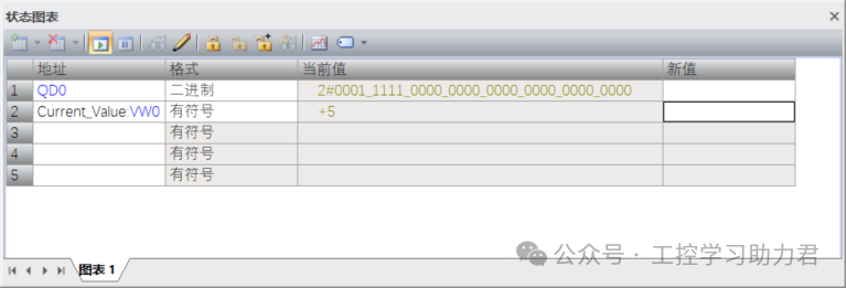
Test Step 1: Use the “Force” function of the programming software to assign a value of 5 to VW0, setting the target output bit count to 5.
Test Step 2: Trigger the I0.0 start signal and observe the state of the QD0 register. The monitoring results show that the lowest 5 bits of QD0 (Q0.0-Q0.4) are in the “1” state, while the remaining 27 bits are “0,” perfectly matching the value set in VW0.
Subsequent supplementary tests: Assign values of 10, 20, and 32 to VW0, repeating the above operations, and the corresponding number of output bits in QD0 can be accurately activated, with fast response speed, no delays or erroneous actions, verifying the reliability of the program.
5. Extended Thoughts: Expansion Solutions to Break the 32-Bit Limitation
The above program is based on 32 output bits, but in actual industrial scenarios, there may be output requirements exceeding 32 bits (such as needing to control 40 or 50 output bits). In this case, relying solely on one double word register (QD0) is insufficient, and the program needs to be expanded, with the core idea being “multiple register splicing + loop segment control.”
Specific expansion directions include:
-
Register Grouping: Divide the output exceeding 32 bits into multiple double word groups, such as QD0 (Q0.0-Q3.7), QD4 (Q4.0-Q7.7), QD8 (Q8.0-Q11.7), etc., with each double word corresponding to 32 output bits.
-
Value Splitting: Split the total number of output bits in VW0 into “complete double word count” and “remaining bits.” For example, if VW0=40, it can be split into “1 complete 32-bit (QD0) + 8 remaining bits (the first 8 bits of QD4).”
-
Nested Loops: Add an outer FOR loop to control the switching of double word registers, while the inner loop controls the number of shifts within each double word. By checking whether the remaining bits are 0, achieve continuous activation of multiple registers, thus breaking the 32-bit limitation.
This expansion solution retains the core advantages of “FOR + SHBR,” and by simply adding register grouping logic, it can adapt to any number of output requirements, further enhancing the program’s scalability.
6. Conclusion: The “Efficiency Thinking” of PLC Programming
From the student’s “stacking of comparison instructions” to the “FOR + SHBR combination optimization,” the core insight of this case is that PLC programming should not only achieve functionality but also pursue an efficiency mindset of “simplicity, flexibility, and scalability.” When facing batch control requirements, priority should be given to instructions with “batch processing capabilities” such as loops and shifts, rather than being limited to basic point-to-point instructions.
For S7-200 SMART users, the “controllable number of iterations” of the FOR loop and the “continuous activation feature” of the SHBR shift register form an efficient combination, applicable not only to the multi-output control scenarios discussed in this article but also extendable to similar needs such as LED indicator light flow control and multi-station triggering on conveyor belts. Mastering such instruction combination techniques can significantly enhance programming efficiency, making programs more industrially practical.
Since you’ve read this far, why not follow and give a thumbs up? The more people who share and like, the more motivated I am to update!