1. Introduction
HMI (Human-Machine Interface) is increasingly used in industrial automation systems and equipment due to its small size, high performance, and strong real-time capabilities. It features various displays such as letters, Chinese characters, graphics, and images, with a simple and user-friendly interface. Equipped with long-lasting membrane button keyboards, it is easy to operate. Typically, it uses microcontrollers with high integration, fast speed, high reliability, and low cost as its core controller to achieve real-time rapid processing. The combination of PLC and microcontroller not only enhances the data processing capability of the PLC but also provides users with a friendly and simple interface. This article discusses in detail how to implement communication between a microcontroller and a PLC using the Modbus communication protocol as an example.
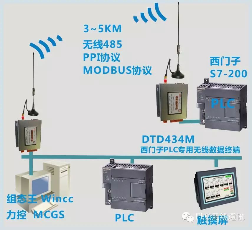 2. Modbus Communication Protocol
The Modbus protocol is a universal language used in electronic controllers. Through this protocol, controllers can communicate with each other and with other devices via the network.
The Modbus protocol provides a master-slave principle, meaning that only one device (the master) can initiate transmission (query). Other devices (slaves) respond according to the data provided by the master device. The format of the master device’s query includes: device address (or broadcast, which does not require a response), function code, all data to be sent, and an error detection field. The response message from the slave device includes the confirmation address, function code, any data to be returned, and an error detection field. If an error occurs during message reception, or if the slave device cannot execute the command, the slave will generate an error message and send it as a response.
The controllers can be set to two transmission modes: ASCII and RTU. At the same baud rate, RTU can transmit more data than ASCII, so the KTU mode is used.
(1) Typical RTU Message Frame
A typical RTU message frame is shown in Table 1.
 The address field of the RTU message frame contains 8 bits. Possible slave device addresses range from 0 to 127 (decimal). Address 0 is used as a broadcast address so that all slave devices can recognize it. The master device selects the slave device by placing the address of the slave device in the address field of the message. When the slave device sends a response message, it places its address in the response’s address field so that the master device knows which device is responding.
The function code field in the RTU message frame contains 8 bits. When the message is sent from the master device to the slave device, the function code field informs the slave device what actions to perform; when the slave device responds, it uses the function code field to indicate whether the response is normal (no error) or if an error has occurred (called an exception response, generally by changing the highest bit of the function code from 0 to 1).
The data field of the message sent from the master device to the slave device contains additional information: the data that the slave must use to execute the actions defined by the function code. This includes non-continuous register addresses, the number of items to be processed, and the actual number of data bytes in the field. If no error occurs, the data field returned from the slave contains the requested data. If an error occurs, this field contains an exception code that the master device application can use to determine the next action to take.
When using RTU mode for character frames, the error detection field contains a 16-bit value (implemented using two 8-bit characters). The contents of the error detection field are derived through a cyclic redundancy check (CRC) method applied to the message content. The CRC field is appended to the end of the message, with the low byte added first followed by the high byte.
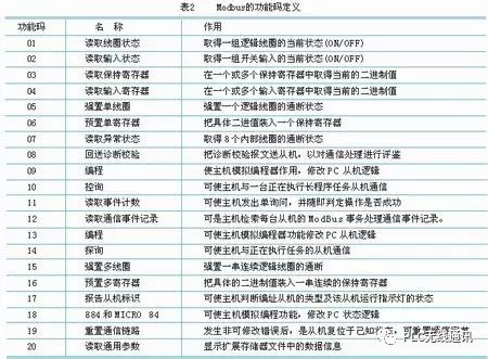
(2) All Modbus Function Codes
The function codes of Modbus are defined in Table 2.
3. Design of Common Function Communication Programs
This article introduces the design of several commonly used Modbus function programs. The author uses a microcontroller as the master and writes programs on the microcontroller to achieve communication between the microcontroller and the PLC. The microcontroller sends command information to the PLC, which responds automatically. The PLC communicates through the serial communication port of the microcontroller, and the program is implemented using C51. The sub-functions of the program and their functionalities are as follows:
(1) Serial Port Initialization
void ProtocolInit(void)
Functionality: Sets the serial port to asynchronous communication mode 1 (1 start bit, 8 data bits, 1 stop bit); sets timer/counter 1 as the baud rate generator with a communication speed of 9600 bps; enables serial interrupts and sets the serial interrupt to high priority. (2) Simple CRC Function
unsigned char Crc16(unsigned char *puchMsg, unsigned char usDataLen)
Functionality: Initializes a 16-bit register with all bits set to “1”, then processes each consecutive 8-bit byte in the message with the current value in the register. Each 8-bit character is ORed with the register content, the result is shifted towards the least significant bit, and the most significant bit is filled with 0. The LSB is checked; if it is 1, the register is ORed with a preset value; if it is 0, nothing is done. This process is repeated 8 times. After the last bit (the 8th bit) is completed, the next 8-bit byte is ORed with the current value of the register. The final value in the register is the CRC value after all bytes in the message have been processed.
(3) Initialize Variables
void Initvar(void)
Functionality: Initializes all process variables.
(4) Serial Interrupt Service Program
void ProtocolSerialProcess(void) interrupt 4 using 2
Functionality: Sends the command array formed by the interrupt from the master, sets the flag after sending; receives the response array returned by the PLC, stores it in the receive array, sets the flag, and assumes the response is correct, waiting for the master to process.
(5) Read N Bits Variable (Coils)
void ProtocolRead_bit(unsigned char DeviceAddr /* PLC Address */, unsigned char RegType /* Register Type */, unsigned int BitAddr /* Starting Address */, unsigned char SubAddr /* Sub Address */, unsigned int BitNum /* Number of Bits */)
Functionality: Forms the command array to read N bits variable based on function parameters and initiates sending. Waits for completion and reception (if timeout occurs before complete reception, resend). Analyzes the receive array: if correct, saves the read data; if erroneous, resends.
(6) Write a Bit Variable
void ProtocolSetBit(unsigned char DeviceAddr /* PLC Address */, unsigned char RegType /* Register Type */, unsigned int BitAddr /* Address */, unsigned char SubAddr /* Sub Address */, unsigned int ClrSet /* Write value “1” or “0” */)
Functionality: Forms the command array to set a bit variable to “1” or “0” based on function parameters and initiates sending. Waits for completion and reception (if timeout occurs before complete reception, resend). Analyzes the receive array: if correct, returns; if erroneous, resends.
(7) Read N Bytes Variable
void ProtocolReadByte(unsigned char DeviceAddr /* PLC Address */, unsigned char RegType /* Register Type */, unsigned int RegAddr /* Starting Address */, unsigned char SubAddr /* Sub Address */, unsigned int RegNum /* Number of Variables */)
Functionality: Forms the command array to read N bytes variable based on function parameters and initiates sending. Waits for completion and reception (if timeout occurs before complete reception, resend). Analyzes the receive array: if correct, saves the read data; if erroneous, resends.
(8) Write N Bytes Variable
void ProtocolSetByte(unsigned char DeviceAddr /* PLC Address */, unsigned char RegType /* Register Type */, unsigned int RegAddr /* Starting Address */, unsigned char SubAddr /* Sub Address */, unsigned int RegNum /* Number of Variables */)
Functionality: Forms the command array to write N bytes variable (the values to write are read from a parameter array), initiates sending. Waits for completion and reception (if timeout occurs before complete reception, resend). Analyzes the receive array: if correct, returns; if erroneous, resends.
4. Conclusion
The above programs have been tested and applied in actual human-machine systems. Following similar methods, other function programs can be written to achieve different controls and operations on the PLC. Utilizing the advantages of both the microcontroller and PLC can form a networked, intelligent industrial control system. Furthermore, the entire microcontroller system program is programmed in C51, making the program concise and easy to read and debug. The combination of the microcontroller and human-machine interface can display the working status of the PLC in real-time, control, set, and adjust the PLC working conditions in real-time, improving the level of automation and real-time performance in industrial control.
Source: PLC Wireless Communication
Link: How to Become an Industrial Robot Application Engineer?
We are not just carriers of dry goods

Only a step away from being an industrial robot expert
Guide Car Robot Academy, a cradle for robotic craftsmen
< Previous Classic Articles >
-
Foxconn Automation Production Line Video, A Visual Feast!
-
Huawei Automation Production Line, Stunning!
-
Advanced Automated Conveyor Belt!
-
What Does the Future Smart Workshop of Steel Mills Look Like?
-
Fully Automated Cigarette Production Line, Amazing!
-
Working Principles of Various Sensors in Animated GIFs, Valuable Content!
-
10 Workers + 386 Robots, Producing 80 Cadillacs Daily!
-
What’s so great about automated chicken and pig slaughter? Come see automated fish slaughter!
-
Five Major Misconceptions in Factory Automation Transformation, Avoid at All Costs