The communication routine for Schneider PLC involves three function blocks: ADDM, READ_VAR, and WRITE_VAR. Below, I will introduce each of them.
1 ADDM
The ADDM function block is for address conversion, which converts the physical address of the PLC into an address type recognizable by the PLC. To put it simply, it converts a string variable into an ADDRESS type variable. Let’s look at an example.
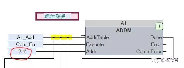
Figure 1 ADDM Function Block
As shown in Figure 1, the red circle contains a string variable ‘2,1’. The first number 2 indicates serial port 2 of the PLC, and the second number 1 indicates the address of the slave device, which is the address of the inverter. This function block converts this address into an ADDRESS type variable A1_Add. You might wonder why this is done. I don’t know either; this is just how this PLC works, and we have to remember this routine. In other PLCs, especially Japanese ones, this is generally achieved by setting parameters, or sometimes using instructions.
Another point is that the three black dots highlighted with a yellow marker indicate that the circuit is connected, and they assign the converted address to the function block we will introduce next. In other words, the read/write function block uses the variable A1_Add to read or write the slave device’s address.
2 WRITE_VAR
This function block is used to write data to the slave, specifically to write the operating frequency to the inverter.
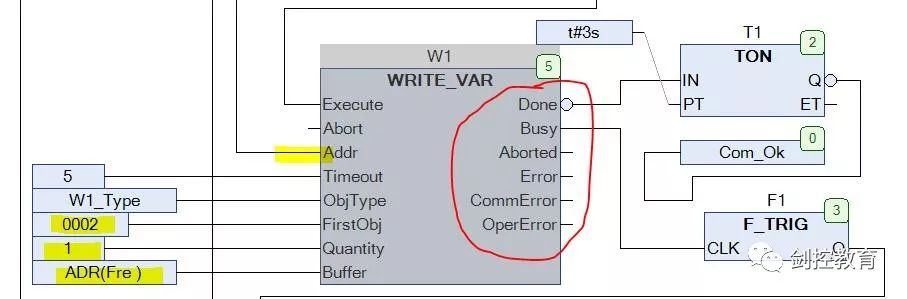
Figure 2 WRITE_VAR Function Block
This function block carries a lot of information, so let’s analyze it step by step.
1 Look at the yellow highlighted part Addr; this is the address of the slave, which is the address of the inverter. It is an ADDRESS type variable, which is converted in the ADDM function block, represented by the three black dots in Figure 1, which are connected to this point. This is also an advantage of CFC, where you can easily connect the variables you need. In FBD or LD, we would need to establish an intermediate variable to pass it.
2 The three parts highlighted below represent the essence of this function block. It indicates that a WORD type variable is written starting from the inverter address 0002, and the written value is stored in the PLC variable Fre. This is the purpose of this function block and the goal of this communication; the execution result is that the value of the PLC variable Fre is written into the inverter at address 0002. Of course, here we only wrote one WORD; in fact, this function block supports writing up to 125 at once because Quantity is an SINT type variable. Fre is an array type variable, which makes it convenient when we want to write many values at once.
3 The red circle on the right is the output of the function block, which indicates various states of the function block execution. It is a standard PLCopen signal.
Done indicates that the function block executed normally and is set to TRUE. Here, we take its inverse signal to monitor the communication status. If there is no Done signal for more than 3 seconds, we can consider this write operation failed, which means communication failed.
Busy indicates the output of the function block execution status. If it is high, it means the function block is executing. We read its falling edge to trigger the next operation.
Error indicates an error in the function block. You might wonder why we don’t use this signal for communication errors? Actually, this error has a broader range; it indicates that the function block detected an error and triggered an alarm. Sometimes, our communication is normal, but if the data we read is incorrect or the parameters are set improperly, it will also raise an error. In my program, the error I monitor is only for communication failures, so this Error is more suitable for monitoring during debugging. The communication error I monitor is done on the upper computer.
3 READ_VAR
The READ_VAR function block is exactly the same as the WRITE_VAR function block; you can try analyzing it yourself.
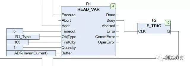
Figure 3 READ_VAR Function Block
4 Data Processing
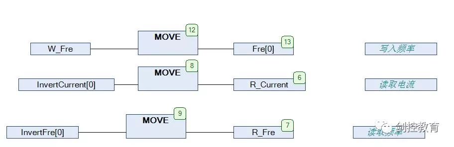
Figure 4 Data Processing
This part is directly related to us in the program. The written frequency, read frequency, and current are all processed using the MOVE instruction and placed into designated variables for our use. After all, the ultimate goal of communication is to exchange data.
Set communication parameters (mainly baud rate, parity, address), and ensure that the parameters on both the PLC and inverter sides are consistent. The addresses, quantities, and data types of the variables to be read or written (Japanese PLC does not require this step since it does not define variables) are the basic routine of MODBUS. When you use different PLCs, your task is to find where to implement these functions in the software to complete the communication. One more thing to note is that different manufacturers have different MODBUS interfaces, commonly DB9, RJ45, and the simplest screw terminals.
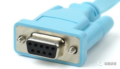
Figure 5 DB9
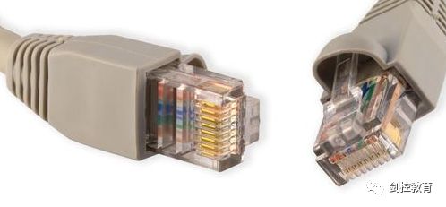
Figure 6 RJ45
As shown in Figures 5 and 6, these are commonly used MODBUS wiring terminals. When using, be sure to read the manual carefully to determine the positive and negative terminals.
(Source: Internet, copyright belongs to the original author)
Disclaimer: This article is a network reprint or adaptation, and the copyright belongs to the original author. If there are any copyright issues, please contact for deletion! No individual or organization shall bear relevant legal responsibilities.
Click to read the original text for more surprises