(Thanks to everyone for your support and appreciation. If this article resonates with you, please “like” and “recommend” it. Thank you all!)
Task Introduction
In a certain community’s secondary water supply system, to ensure that every household receives normal water supply and to maintain the stability of water flow, a constant pressure water supply design was adopted. It requires the use ofPLC, pressure transmitters, and frequency converters to achieve constant pressure water supply control.
01 Hardware Circuit Design
The hardware circuit for constant pressure water supply is shown in the figure below.
 The following image shows the physical pressure transmitter.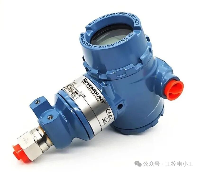
02 Project Knowledge Reserve
1. Understanding Analog Closed-Loop Control Systems
The workflow of an analog closed-loop control system is illustrated in the figure below.

(1) The controlled variable c(t) is a continuously changing analog quantity, which is first converted by the measuring element sensor and transmitter into a standard range current signal or voltage signal pv(t);
(2) The pv(t) is converted into a digital quantity pv(n) by the AD converter in the analog input module;
(3) sp(n) is the setpoint, and pv(n) is the feedback quantity after AD conversion;
(4) The error is ev(n)=sp(n)-pv(n).
(5) The D/A converter converts the digital output mv(n) from the PID controller back into an analog quantity mv(t), which then controls the actuator, forming a closed-loop control system.
Application Case: In the constant pressure water supply closed-loop control system, the pressure transmitter detects the pressure value in the pipeline, converting the pressure into a standard range current or voltage, which is then sent to the analog input module. After AD conversion, a digital quantity proportional to the pressure is obtained. The CPU compares it with the pressure setpoint and performs calculations on the error value according to a certain control law, sending the result to the analog output module. After D/A conversion, it becomes a current or voltage signal used to control the frequency of the frequency converter, thereby controlling the flow of the pump and achieving closed-loop pressure control.
2. Understanding PID Controllers
PID is an abbreviation for Proportional, Integral, and Derivative.
The role of P is to increase the output value proportionally to the control deviation;
The role of I is to continuously increase the output value until the control deviation reaches a balanced state;
The role of D is to increase the derivative action with the rate of change of the control deviation. The process value will quickly correct to the setpoint. If the rate of change of the control deviation decreases, the derivative action will weaken again.
Note: If the PID controller can control the actuator’s action in a process system, thereby affecting a certain process value of the process system, this system is called a controlled system. Properly setting the PID controller parameters can enable the controlled system to reach the setpoint quickly and maintain it constant.
3. Process PID Control
In the process, PID control includes PID_Compact, PID_3Step, and PID_Temp.
Among them:
-
PID_Compact is a general-purpose PID controller integrated with regulation functions;
-
PID 3Step is a general-purpose PID controller integrated with valve regulation functions;
-
PID Temp is a temperature PID controller.
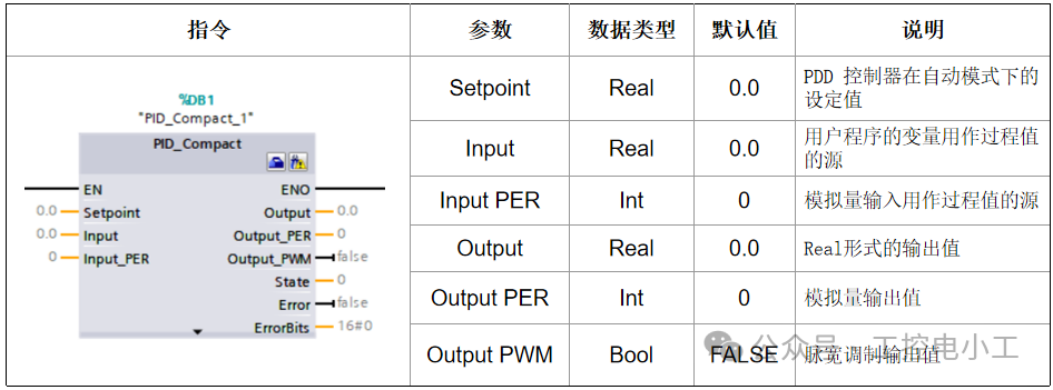
The pin definitions of the PID controller are shown in the table below.
03 Project Implementation
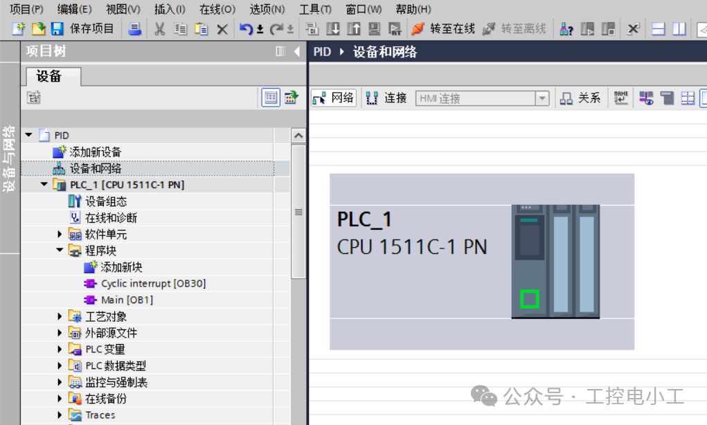
(1) Create a project, insert the CPU 1511C-1PN controller, and add the cyclic interrupt organization block [OB30], as shown in the figure below.
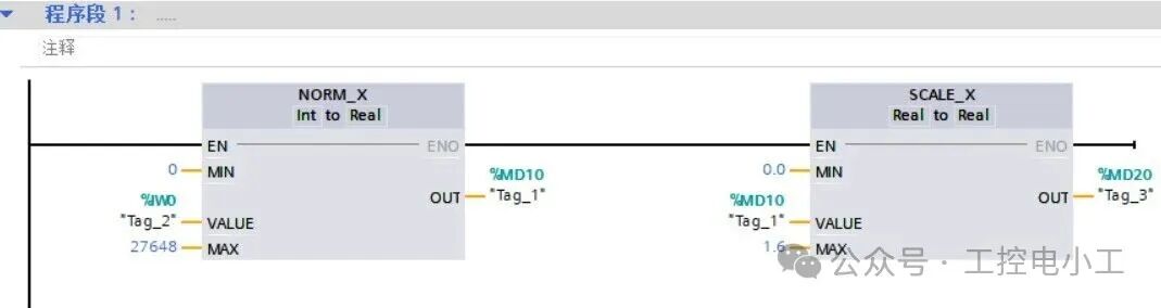
(2)In Main[OB1], write the normalization and scaling program, storing the normalization results in MD10 and the scaling results in MD20, as shown in the figure below.
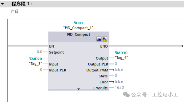
(3)In the cyclic interrupt organization block[OB30], call PID Compact, click on “Process” to open the extension, select “PID Control” in PID Compact, and drag it into the program segment, automatically generating the background data block DB1. Set the Setpoint pin input value to 0.5, Input memory address to MD20, and Output memory address to MD30, as shown in the figure below.
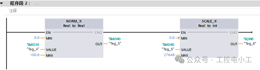
(4)Use the output of the PID controller to control the frequency converter. In Main[OB1], write the normalization and scaling program, storing the normalization results in MD40, and outputting the scaling results to QWO, as shown in the figure below.
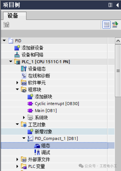
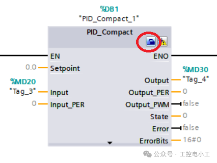
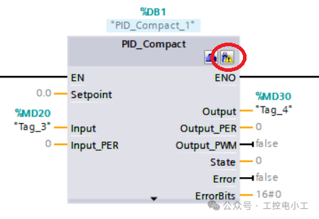
(5)Configure the PID, which can be accessed from the configuration options of the process object PID Compact 1[DB1] in the project tree, or by clicking the three icons in the upper right corner of the controller in the program segment to enter the settings, as shown in the figure below.
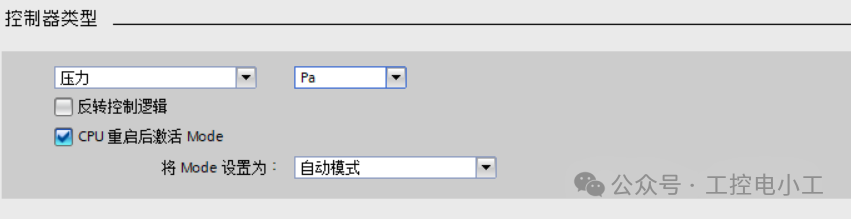
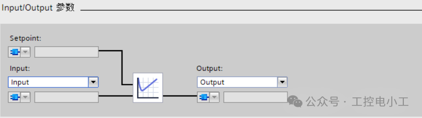
(6)Basic Settings: Controller type is pressure, unit is Pa, and activate Mode is automatic after CPU restart; Input/Output parameters: select Input and Output, as shown in the figure below.
(7)Set process value limits and process value monitoring, and download the program to the PLC.
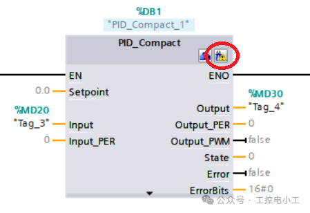
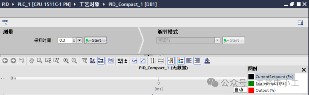
(8)Debug the PID, which can be accessed from the debugging options of the process object PID_Compact_1[DB1] in the project tree, or by clicking the icon in the upper right corner of the controller in the program segment to enter the settings, as shown in the figure below.
(9)Click on the Start icon in “Measurement”; after the program starts running, click on the Start icon in “Adjustment Mode” to perform automatic adjustment. The adjustment status will display that it is in progress, and when approaching the setpoint, it will begin precise adjustments, as shown in the figure below.
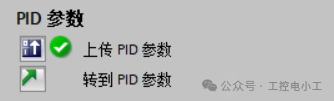
(10) When the precise adjustment is completed, the adjustment status will display that the system has been adjusted. Upload the PID parameters, and when the green checkmark appears, the parameters have been successfully uploaded, as shown in the figure below.
1
END
1
Previous Reviews
Practical Case: Two S7-1200 PLCs Achieve PROFINET Communication, Detailed Steps Included, All Programs Provided for Easy ImplementationPractical Case | S7-1200 Cycle Color Light Control, Complete Source Program Included for Easy Replication!Must-Know for Senior Electricians: Siemens S7-1200 PLC Controlled Automatic DoorMust-Know for Senior Electricians: Siemens S7-1200 PLC Controlled Traffic Light at IntersectionsMust-Know for Senior Electricians: Siemens S7-1200 PLC Controlled Automatic Assembly LineMust-Know for Senior Electricians: Siemens S7-1200 PLC Controlled Automatic Mail Sorting Machine
If you likeIndustrial Control Electrician‘s articles, please click on the business card to follow me! I will continue to share technical insights about PLCs and industrial robots!