Have you ever faced the problem of forgetting to drink from your kettle after boiling water, only to find it has cooled down? If you want to enjoy warm water without having to reboil, we can use a bit of technology to transform a regular kettle into a “temperature control device”. Today, I will guide you through using a PLC to achieve this functionality, and even if you are a beginner, you can follow the steps to get it done!
1. Let’s Discuss the Desired Outcome
A regular kettle at home can only boil water once and then stops; when the water cools down, you have to manually reheat it. This time, we will use a PLC for control to solve the “quick cooling” problem, specifically achieving two core requirements:
- When the start button is pressed for the first time, the kettle begins to heat, and it automatically stops when the water temperature reaches 100℃;
- After that, as long as the water temperature drops below 30℃, it will automatically start heating again, maintaining a drinkable temperature;
- No matter when, pressing the stop button will immediately cut off the power, safety first!
To complete this small project, we need to prepare several hardware components: a Pt100 thermistor for temperature measurement, a temperature transmitter to convert the temperature signal into an electrical signal, the core Mitsubishi FX5U-32MT/ES PLC, a solid-state relay to control heating, and the heating rod we will modify. When placed together, it looks like this; doesn’t it seem uncomplicated?
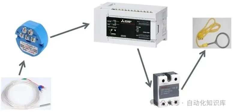
Figure 1-1 Heating System of the Kettle
2. Key Step: How to Set Up the PLC Analog Input Module?
In this project, the PLC needs to “understand” the temperature, which relies on the analog input module — it can convert the temperature signal from the thermistor into a digital signal that the PLC can recognize. This setup is crucial, so let’s go step by step.
01 Basic Settings (Refer to the Images for Clarity)
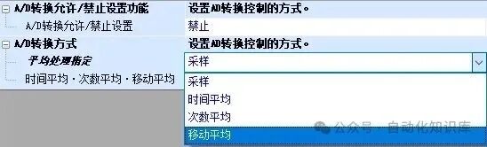
Figure 2-1 Basic Settings for Analog Input
First, we need to allow the PLC to “translate” the temperature signal, which means setting “A/D conversion enable/disable” to “enable”; otherwise, the PLC will receive the signal but won’t be able to process it.
Next, we select the “A/D conversion method”. Simply put, this is how the PLC collects temperature data. Here are the four methods explained, and we can choose based on our needs:
- Sampling: The PLC collects temperature data once every time it “scans” the program, which is fast;
- Time Averaging: For example, sampling every 10 seconds and taking the average over that period, which stabilizes the data;
- Count Averaging: Collecting data 10 times, summing it up, and dividing by 10, suitable for interference-prone scenarios;
- Moving Average: For example, setting it to 4 times, each time sampling new data while discarding the oldest, then calculating the average (as shown in the image), balancing speed and stability.
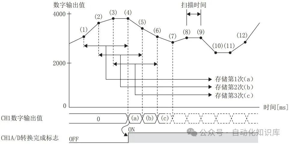
Figure 2-2 Moving Average
02 Application Settings (Don’t Miss These Details)
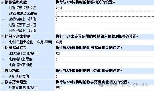
Figure 2-3 Application Settings
This part makes the PLC’s “translation” more accurate, and we will discuss each one:
- Alarm Output Function: For example, if we set the normal temperature range to be 0-150℃, if it exceeds this range, the PLC will automatically light up an alarm (or trigger other notifications), effectively adding a “safety valve” to the device;
- Scale Exceed Detection: When the input voltage signal exceeds 10.2V, the PLC will alert “signal exceeded” to avoid inaccurate data;
- Scale Setting: This is particularly crucial! For example, if the temperature transmitter sends 0V corresponding to 0℃ and 10V corresponding to 150℃, we need to let the PLC know that “0V=0℃, 10V=150℃” by setting the conversion relationship here (see the image), so that the numbers displayed by the PLC are understandable temperatures;
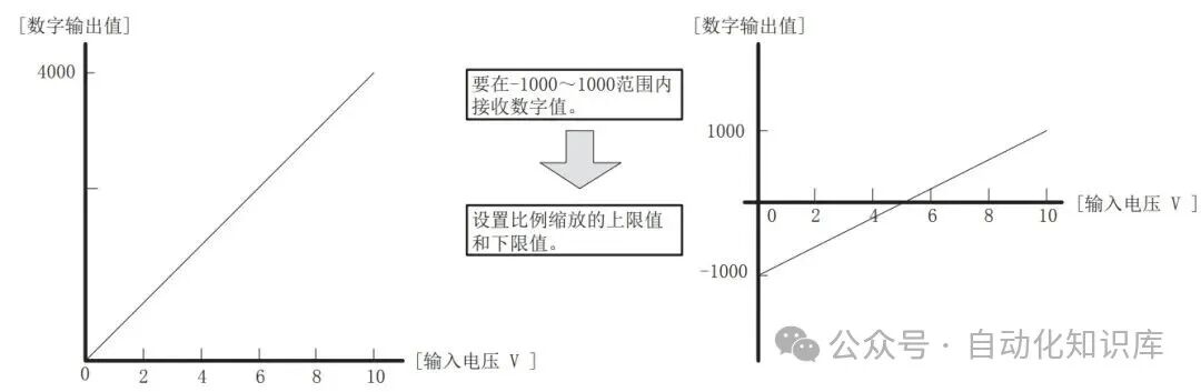
Figure 2-4 Scale Setting
- Offset Function: If the final displayed temperature is consistently a bit off, for example, always 2℃ lower than the actual, this function can be used to “shift” the values to correct them;
- Digital Clipping Setting: If disabled, the PLC outputs a number range of 0-4095; if enabled, it is 0-4000, generally, it is better to keep it disabled for a wider range.
3. Hands-On Practice: From Component Selection to Programming, Not Missing a Step
After discussing the theory, we will move on to the practical part. The entire project will follow these five steps: “selecting components → assigning addresses → wiring → setting parameters → writing programs”. I will explain every detail, and you can follow along.
01 Selecting the Right Components (With a List)
We need to choose suitable components based on the control requirements. I have compiled a BOM list that you can follow to avoid mistakes: for example, choose the Mitsubishi FX5U-32MT/ES PLC, buttons with self-resetting (one for start and one for stop), a Pt100 thermistor (commonly used in industry, accurate for temperature measurement), and the solid-state relay’s power rating should match the heating rod (for instance, if the heating rod is 1000W, choose a relay rated above 10A).
Table 3-1 BOM List
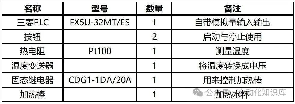
02 Assigning Addresses to the PLC’s Inputs and Outputs
The PLC’s inputs (like the start button and stop button) and outputs (like the control signal for heating) need an “address”, just like a house number, so the PLC can accurately find them. This time, we only use 2 inputs and 1 output, so the assignment table is quite simple:
Table 3-2 I/O Address Assignment Table
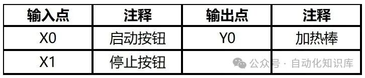
- The start button connects to X0 (equivalent to the PLC’s “start switch”);
- The stop button connects to X1 (the “emergency power cut switch”);
- The control signal for the heating rod outputs from Y0 (sending instructions to the solid-state relay).
03 Wiring: Be Careful, Safety First!
Wiring is a key part of the practical work, and everyone must operate with the power off, so don’t panic! We will discuss it in two parts:
First Part: PLC Input and Output Wiring
The Mitsubishi FX5U’s inputs are very flexible and can connect to either sinking or sourcing, depending on how the S/S terminals are connected:
- If S/S connects to 24V, the input is sinking (which is what we are using this time);
- If S/S connects to 0V, the input is sourcing.
Specific wiring: The start button connects to X0, the stop button connects to X1, and the other end of both buttons connects to 0V; the output terminal Y0 connects to the coil of the solid-state relay, and the other end of the relay coil connects to 24V; one end of the solid-state relay’s normally open contact connects to the heating rod, and the other end connects to the neutral wire, while the other end of the heating rod connects to the live wire (remember to connect a circuit breaker for safety!).
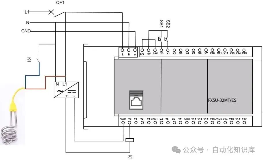
Figure 3-1 PLC Input and Output Wiring
Second Part: Wiring the Temperature Signal
The temperature transmitter requires a 24V power supply, so let’s connect it first. The Pt100 thermistor has three wires: two silver wires can be connected together and connected to the “signal -” of the temperature transmitter, while the red wire connects separately to “signal +”; then connect the output terminals of the temperature transmitter (V1 + and V-) to the V1 + and 0V of the PLC’s analog input, so the temperature signal can be transmitted to the PLC.
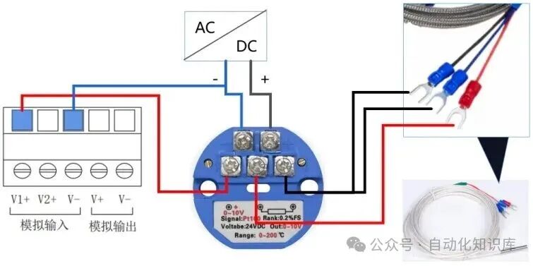
Figure 3-2 Analog Input Wiring
04 Software Parameters: Just Set as Instructed
After wiring, we open Mitsubishi’s programming software (like GX Works3) to set the analog parameters:
-
Basic Settings: Set “A/D conversion enable” to “enable”, and select “sampling processing” (we want to measure temperature in real-time, so a faster response is better);
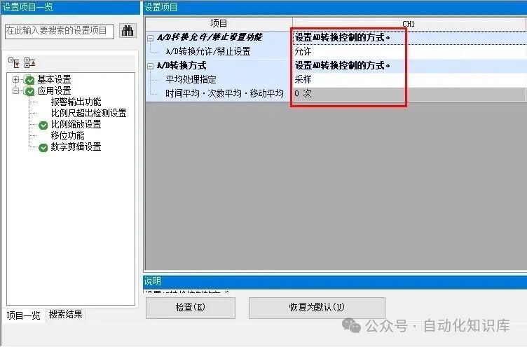
Figure 3-3 Basic Settings for Analog Input
-
Application Settings: As we mentioned earlier, 0℃ corresponds to 0V, and 150℃ corresponds to 10V; we need to fill in this relationship here and then multiply the values by 100 (for example, fill in 0 for 0℃ and 15000 for 150℃), so that the number displayed in the PLC’s SD6021 register, when divided by 100, gives the actual temperature (for example, if it shows 5000, that means 50℃).
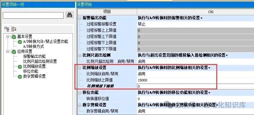
Figure 3-4 Application Settings for Analog Input
05 Writing the Program: Simple “Start-Stop” Logic
The program logic is not complicated; the core is “boil to 100℃ the first time, then start heating again if it drops below 30℃”. This can be achieved using a traditional start-stop circuit:
- Use X0 (start) and X1 (stop) to control M0 (run flag); pressing X0 energizes M0; pressing X1 de-energizes M0;
- When X0 is pressed for the first time, counter C0 counts 1 time, and the normally open contact of C0 closes; if the temperature (SD6021÷100) is less than 100℃, Y0 is energized, and the heating rod operates;
- Once the temperature rises above 100℃, C0 resets; thereafter, as long as the temperature drops below 30℃, regardless of C0’s state, Y0 will energize to heat;
- No matter when, pressing X1 (stop) will de-energize M0, and Y0 will also de-energize, stopping the heating.
The program roughly looks like this; you can refer to the image below:
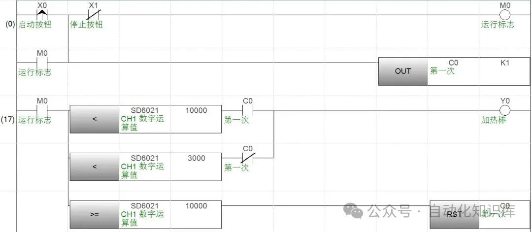
Figure 3-6 Control Program
Final Thoughts
In fact, using a PLC to modify home appliances is not as difficult as you might think — this temperature control for the kettle, from component selection to debugging, can be done step by step, and even beginners can get started. After the modification, you won’t have to repeatedly boil water; in winter, you can enjoy warm water anytime, which is really convenient!
If you encounter any issues during the practical work, such as no response after wiring or inaccurate temperature readings, feel free to ask me in the comments, and we can discuss solutions together. Give it a try, and you will find that PLCs are actually very close to our daily lives!
Previous Recommendations
Using S7-1200 to create a dynamic scale, I broke down the actual engineering case into steps that beginners can understand.
A must-read for electrical engineers! A step-by-step guide to converting electrical diagrams into PLC ladder diagrams.
A must-read for electricians! Two motor nameplates contain key information; an experienced colleague’s breakdown will help you avoid detours.
A hands-on guide! Communicating between Kunlun Tongtai MCGS touch screens and Siemens V20 frequency converters.
Using PLC to control encoder positioning? This article will help you understand the practical logic.
200 PLC shortcut keys have been organized; they can be used from beginner to proficient, and I recommend you save them.
Secrets from experienced workers! 22 tips for handling generator faults; colleagues, be sure to save them.
Want to become an electrician? These 7 things are more important than skills (with 20 high-definition wiring diagrams for electricians).
TIAportalV19 (Step 7) installation tutorial and installation package.
40 essential electrical secondary circuit knowledge that electricians must master.
New to PLC? Check out these 8 motor control examples, including wiring diagrams and programs, packed with useful information.
Among electricians, some earn 3,000 a month while others earn 20,000; the difference lies in choosing the right factory.
6 super practical PLC programs, including traffic lights and elevator control; you can get started after reading!
78 pages of commonly used electrical components PPT, a must-have for electrical engineers! Missing it would be a big loss!
New to PLC: From electrical circuits to ladder diagrams, I will help you avoid the pitfalls I encountered.
Full of useful information, the super practical PLC working principle animation is here; not watching would be your loss!
How to write a PLC program for rotating three motors? A hands-on guide from the teacher.
Electrical assembly for beginners: an ultra-detailed operation guide, step by step, with every detail explained, so you can get started!
A must-read for workers! FANUC robot palletizing programming is surprisingly simple; I will guide you through it for production lines.
37 animated diagrams! The principles of sensors are explained more clearly than textbooks; I recommend saving and studying!
 Share
Share Collect
 View
View LikeFollowSo you can find me next time