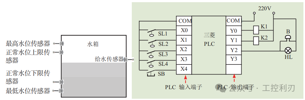
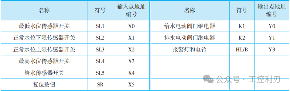
Low water levels in factory production water tanks can affect normal production, while high levels can lead to overflow accidents. Therefore, it is necessary to monitor the water level in the factory water tank in real-time and automatically issue an alarm when the water level is abnormal. The specific requirements for the water level monitoring system are: automatically supply water when the water level falls below the normal lower limit, issue an alarm if the water level is below the minimum level, start draining when the water level exceeds the normal upper limit, and issue an alarm if it exceeds the maximum water level. The diagram shown is the PLC control schematic for the factory water tank level monitoring system (using Mitsubishi PLC as an example). The table shows the I/O allocation table for Mitsubishi PLC.
The I/O allocation table for Mitsubishi PLC
(1) When the water level in the tank is at the normal level, the normal lower limit sensor switch SL2 and the minimum water level sensor switch
SL1 are in a closed state. At this time, the normally closed contact X1 is open, the output coil Y0 is de-energized, the normally closed contact X0 is open, and the timer
is not activated.
(2) When the water level in the tank is between the normal lower limit sensor and the minimum water level sensor, the normal lower limit sensor
switch SL2 is open, the normally closed contact X1 is closed. Since the water supply sensor switch is open, the normally closed contact X4 is in a closed state,
the output coil Y0 is energized, and the relay for the water supply electric valve K1 is activated, starting to supply water to the tank.
At the same time, the normally open contact Y0 is closed to achieve self-locking; when the water level reaches the water supply sensor, the water supply sensor switch closes,
the normally closed contact X4 opens, the output coil Y0 is de-energized, and the relay for the water supply electric valve K1 is de-energized,
causing the water supply electric valve to close and stop supplying water to the tank.
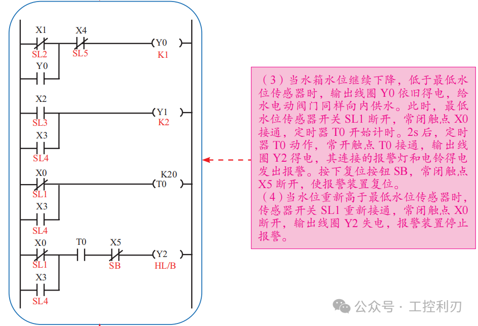
(5) When the water level in the tank is between the normal upper limit sensor and the maximum water level sensor, the normal upper limit sensor
switch SL3 is closed, the normally open contact X2 is closed, the output coil Y1 is energized, and the relay for the drainage electric valve K2
is activated, starting to drain water from the tank. When the water level in the tank falls below the normal upper limit sensor, the normal
upper limit sensor switch SL3 opens, the normally open contact X2 opens, the output coil Y1 is de-energized, and the relay for the drainage electric valve
K2 is de-energized, causing the drainage electric valve to close and stop draining water from the tank.
(6) When the water level in the tank continues to rise, exceeding the maximum water level sensor, the output coil Y1 remains energized, and the drainage electric valve
continues to drain water. At this time, the maximum water level sensor switch SL4 opens, the normally open contact X3 closes, and the timer T0 starts timing.
After 2s , the timer T0 activates, the normally open contact T0 closes, the output coil Y2 is energized, and the connected alarm
light and bell are powered to issue an alarm. Pressing the reset button SB, the normally closed contact X5 opens, resetting the alarm device.
Encouragement

Like before leaving
Previous Recommendations
Understand the meanings of these 9 letters on the contactor, even electrical novices can become experts!
Chengdu BYD Recruitment: Mechanical Technician 6000-7000 RMB
Student unit recruiting maintenance electricians: Comprehensive salary 1.2-1.3W! Real and reliable!
Recruiting 2 maintenance electricians 5k-7.5k
Essential for electrical personnel: Understand PLC output terminals – wiring for these 5 types of components, novices can avoid detours!
Recruiting electrical engineers 8k-13k (home appliance industry)
Can’t find the reason for equipment downtime? PLC program solves external fault diagnosis circuit!
Still can’t understand circuit diagrams? A single circuit diagram teaches you to analyze and interpret!
PLC programming always reports “Invalid Address”? Master these 3 types of storage ranges, and never fall into memory pitfalls again!
A ten-year veteran electrician’s tearful summary: 9 practical rules for electrical equipment!