 Charging Head Network’s 3737th disassembly report.
Introduction
The Security Testing Room has purchased a smart camera from the VIRTAVO brand. This camera features a built-in 400W pixel sensor and a dual-lens design, with one lens mounted on a gimbal and the other fixed at a specific angle, effectively functioning as two cameras in one. The dual lenses can simultaneously address security needs in two different directions and support infrared night vision as well as full-color night vision, catering to both home and commercial requirements.
The two lenses of the camera are divided into a gimbal lens and a fixed lens. The gimbal supports 360° monitoring without blind spots and allows for app selection and alarm notifications, as well as two-way voice intercom and one-way video calls. The camera is equipped with a TF card slot, supports loop recording, and is powered via a USB-C interface. Below, we will present the disassembly of the VIRTAVO smart camera, taking a closer look at its internal design and components.
Appearance of the VIRTAVO Smart Indoor Camera
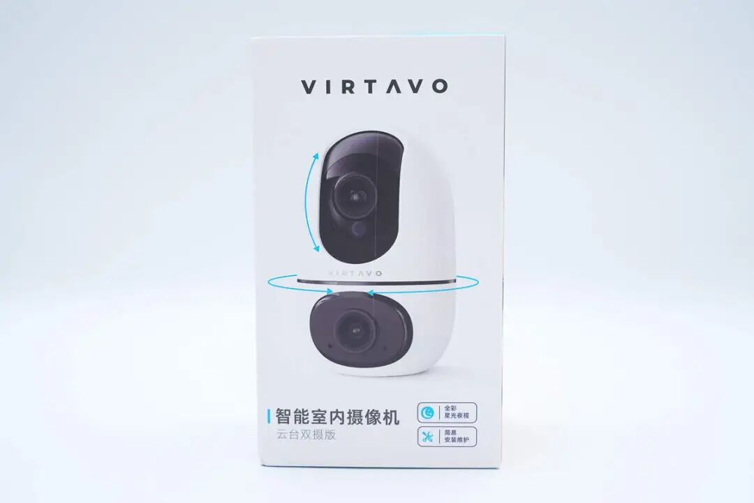
The front of the packaging box features the VIRTAVO brand, an image of the camera product, and the text “Smart Indoor Camera Gimbal Dual Lens Version”.
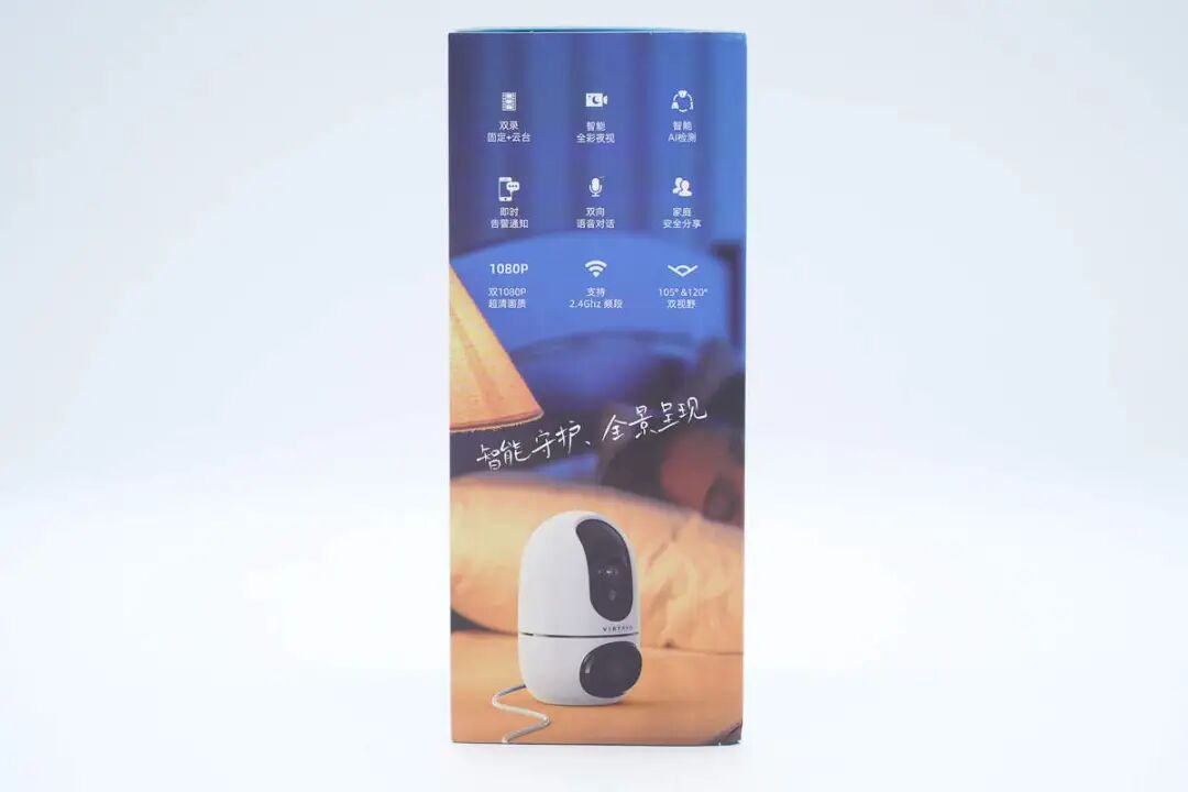
The side of the packaging box lists the camera’s selling points, including fixed + gimbal dual recording mode, smart full-color night vision, intelligent AI detection, instant alarm notifications, two-way voice communication, family safety sharing, dual 1080P ultra-clear quality, support for 2.4GHz frequency band, and dual fields of view of 105° and 120°.
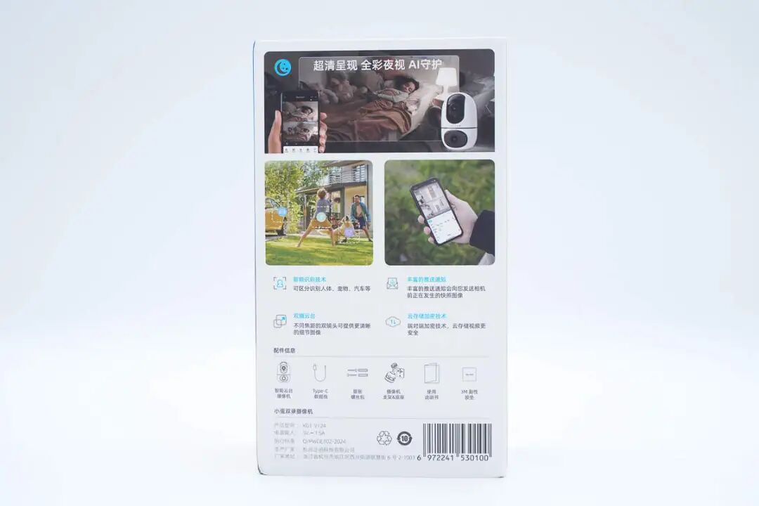
The back of the packaging box describes the camera’s usage scenarios and product features.
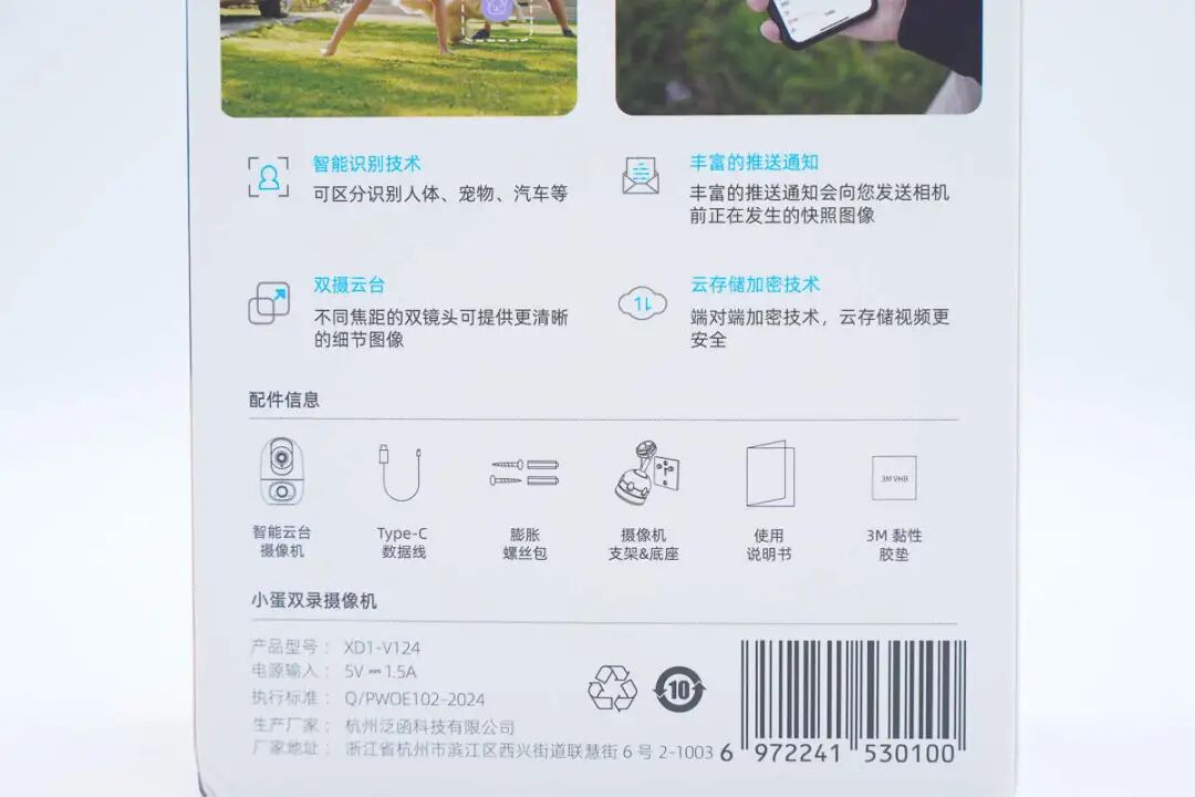
The camera supports intelligent recognition technology, has rich push notifications, supports dual-camera gimbal, and supports cloud storage acceleration technology.
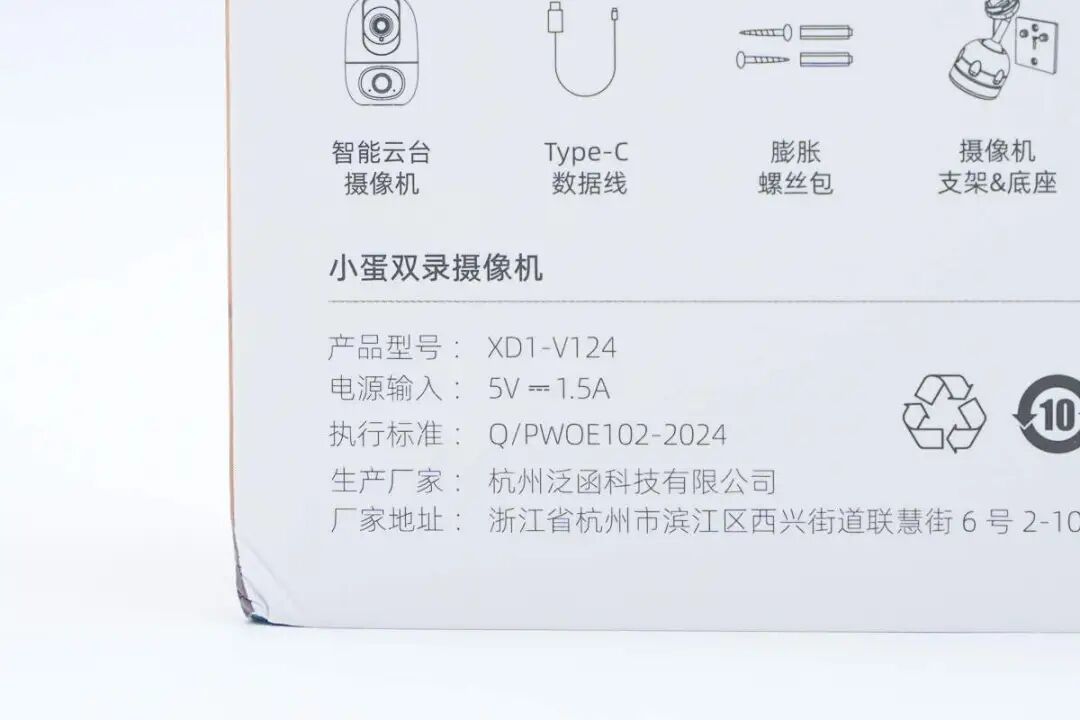
Product Name: Egg Dual Recording Camera
Product Model: XD1-V124
Power Input: 5V 1.5A
Compliance Standard: Q/PWOE102-2024
Manufacturer: Hangzhou Function Technology Co., Ltd.
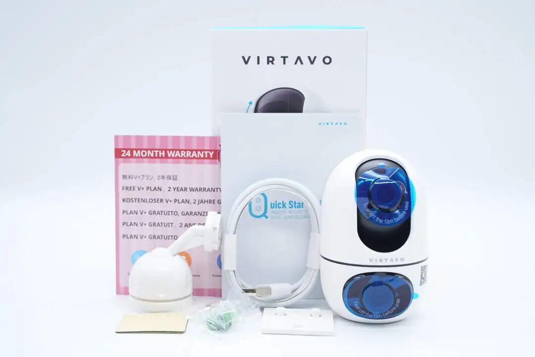
An overview of the items included in the packaging, including the installation base, connection cable, main camera unit, installation mounting plate, expansion screws, as well as the instruction manual and warranty card. The camera lens is protected by a blue plastic film to prevent scratches.
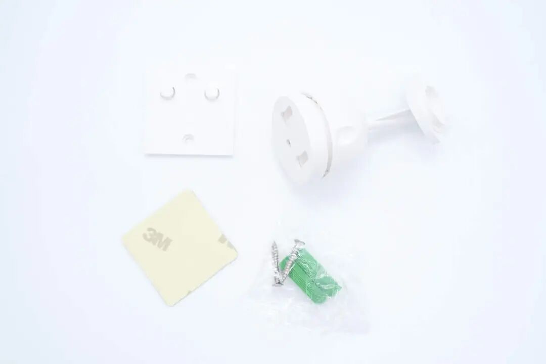
Close-up of the installation mounting plate, double-sided tape, installation base, and expansion screws.
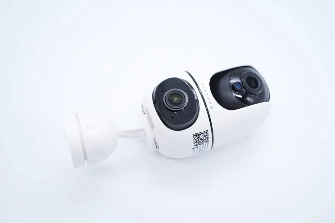
Close-up of the camera installation base.
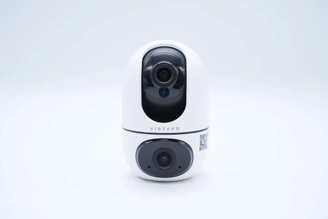
Close-up of the camera placed in a desktop position.
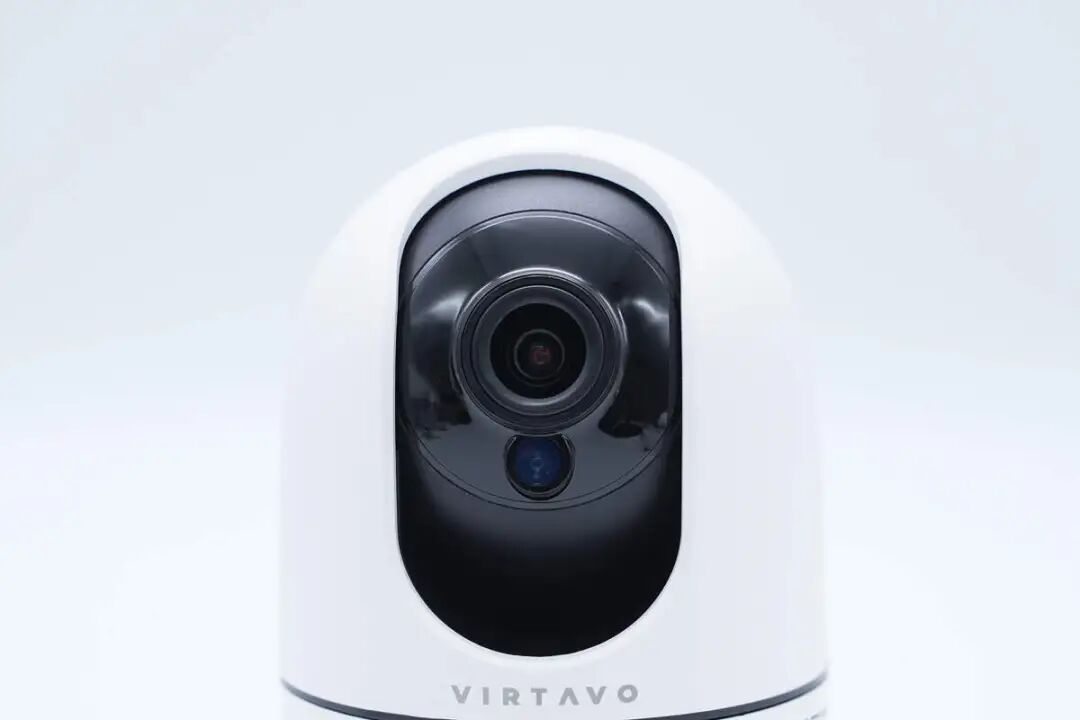
Close-up of the gimbal lens on top of the camera, supporting up and down as well as left and right rotation.
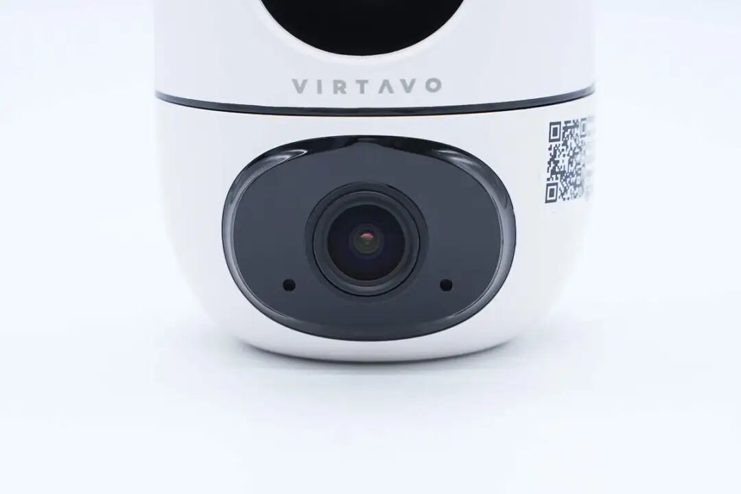
The bottom features a fixed lens, with openings for the microphone and indicator light.
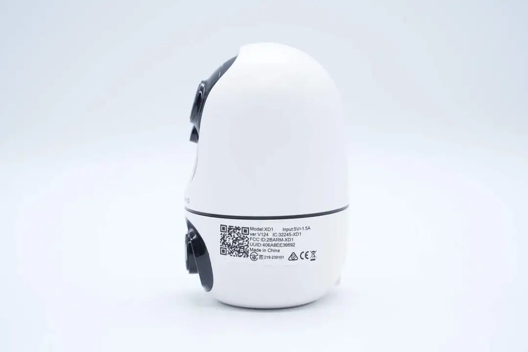
Information label affixed to the side of the body.
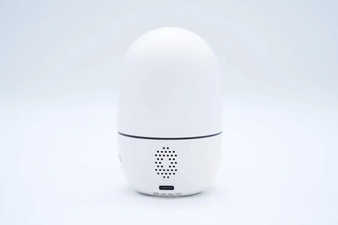
Overview of the back of the body, featuring speaker openings and power supply interface.
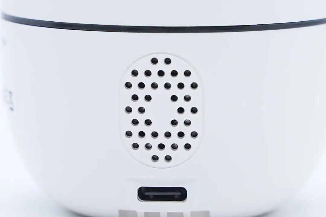
Close-up of the camera’s speaker opening.
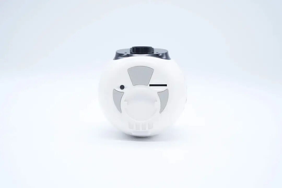
The bottom of the body features a reset button and a TF card slot.
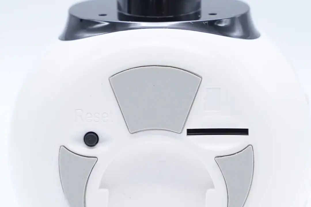
Close-up of the reset button and TF card slot.
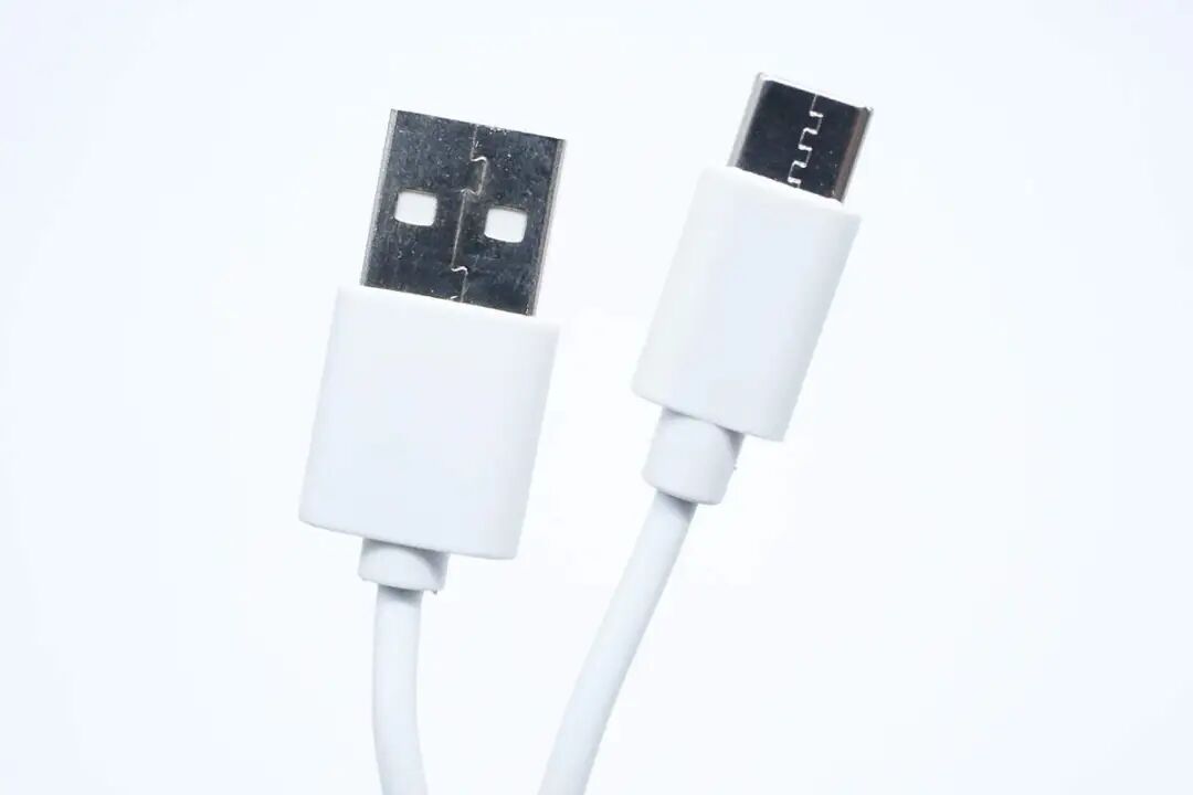
The included connection cable is a USB-A to USB-C interface.
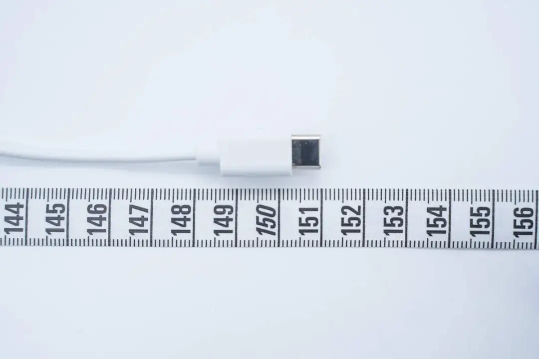
The measured length of the connection cable is approximately 1.5 meters.
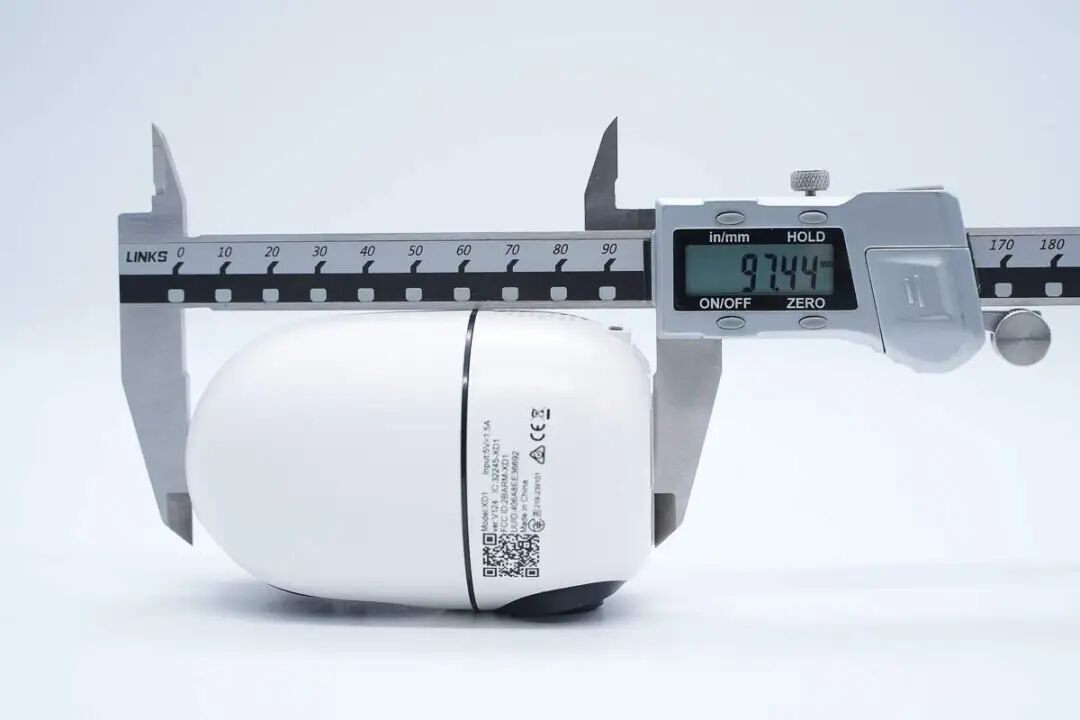
Using a caliper, the height of the camera is measured to be approximately 97.44mm.
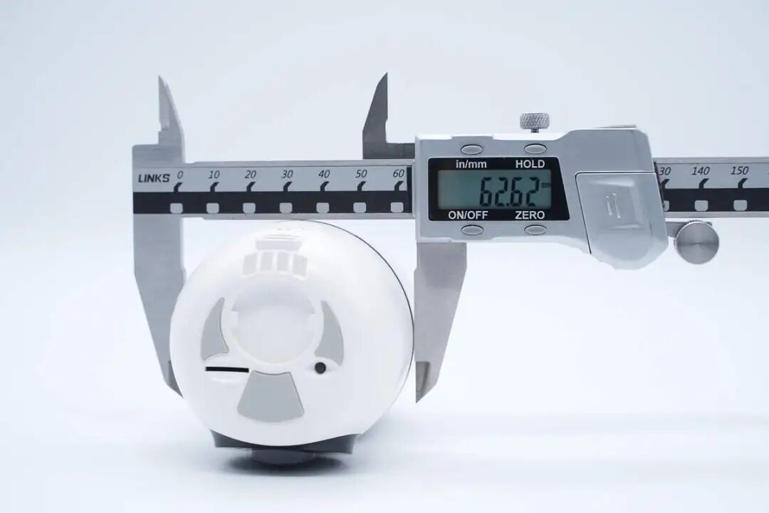
The diameter of the camera body is approximately 62.62mm.
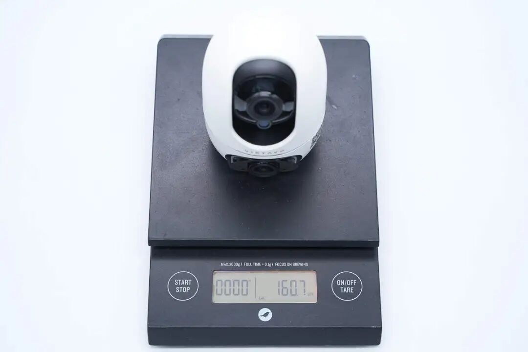
The weight of the camera is measured to be approximately 160.7g.
Welcome to follow the Charging Head Network Testing Room’s official account for more detailed product review reports.
Disassembly of the VIRTAVO Smart Indoor Camera
Having reviewed the exterior of this camera, we will now proceed with the disassembly to examine the internal components and materials.
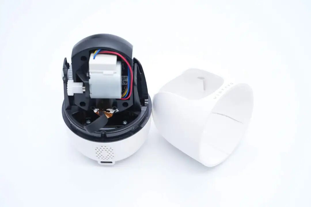
First, remove the plastic outer shell from the top of the camera, revealing a vertically moving stepper motor inside.
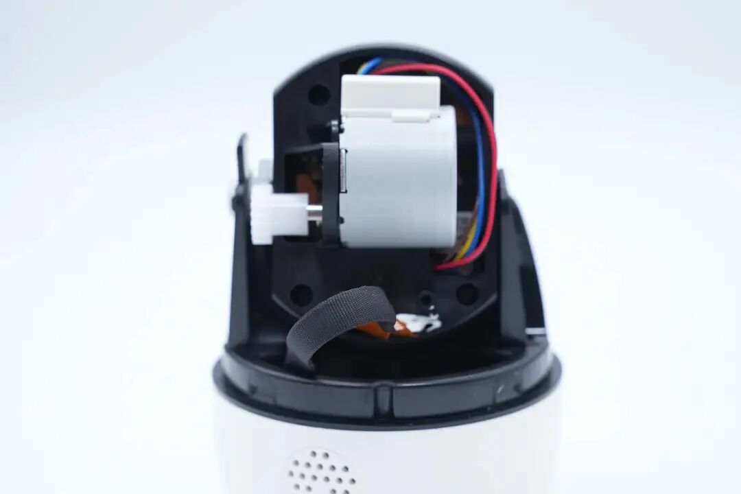
Below the stepper motor is a connection ribbon cable.
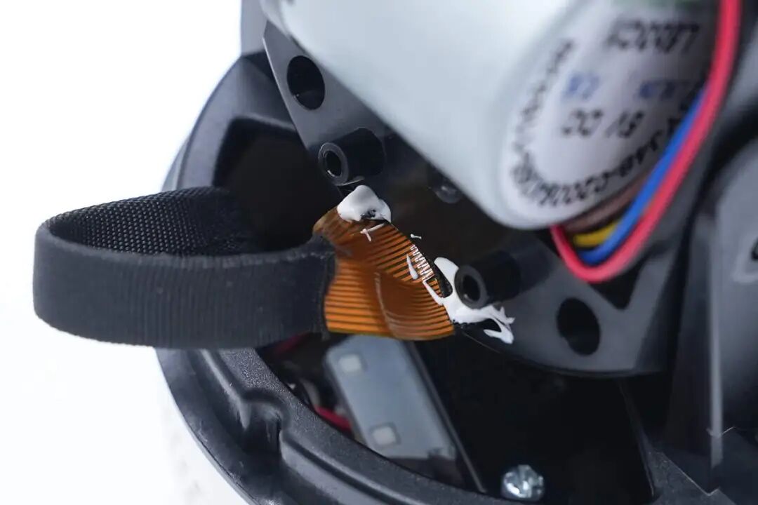
The connection ribbon cable is taped with fabric tape to prevent wear.
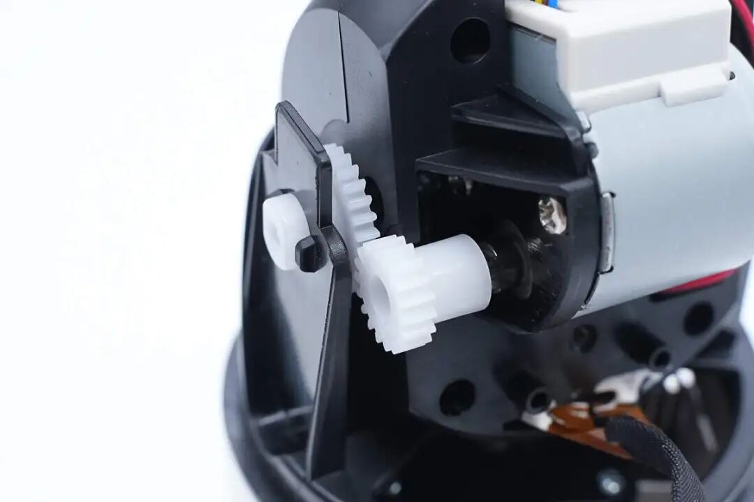
Close-up of the stepper motor drive gear.
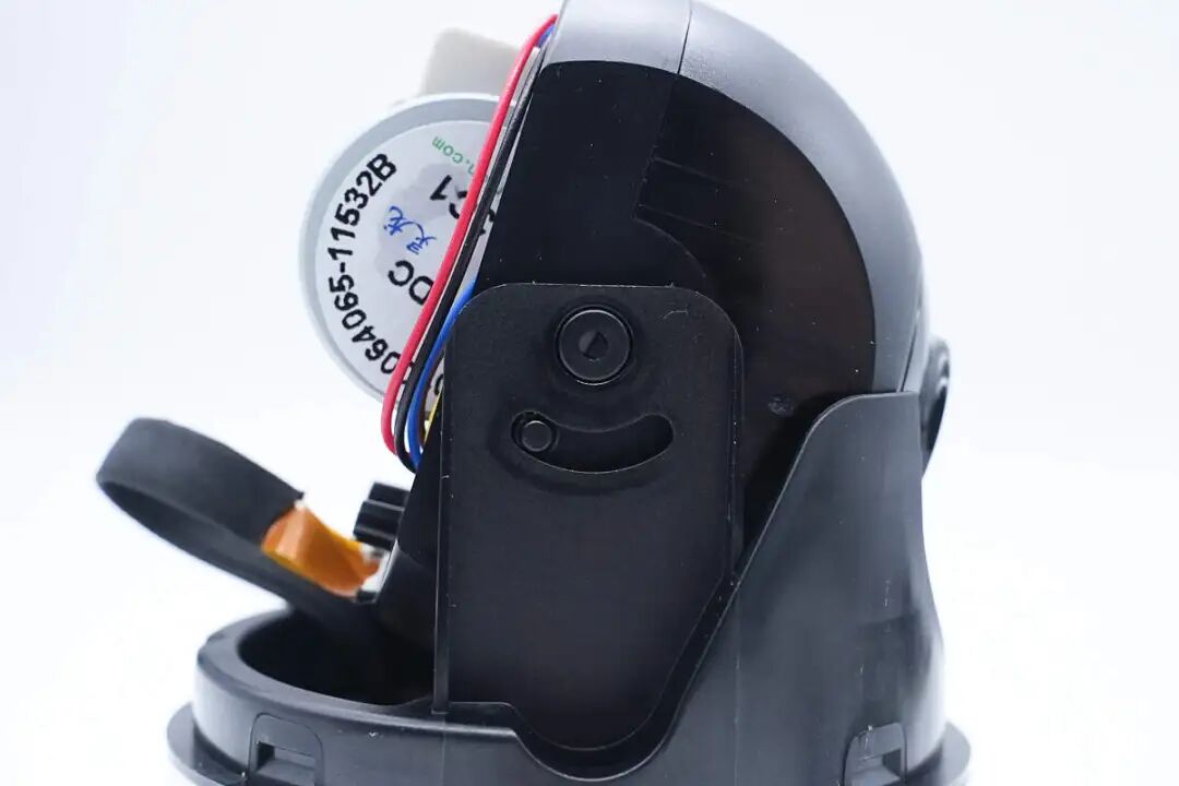
Close-up of the fixed and limiting mechanism on the other side.
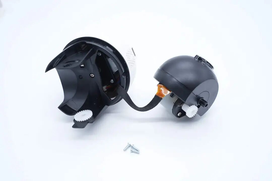
The top camera module is connected to the base via a ribbon cable.
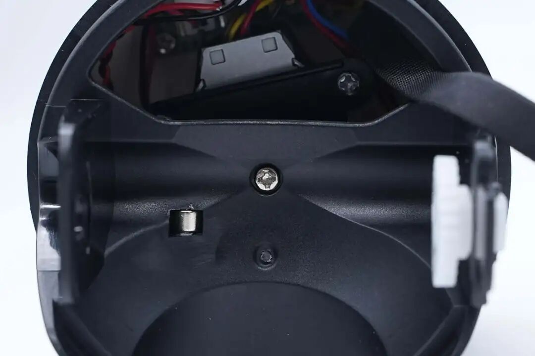
The bottom horizontal gimbal is secured with screws and has magnets for position detection.
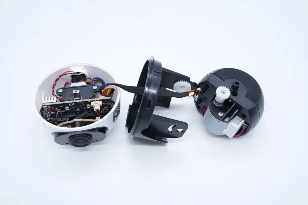
Unscrew the fixed screws to detach the horizontal gimbal from the base.
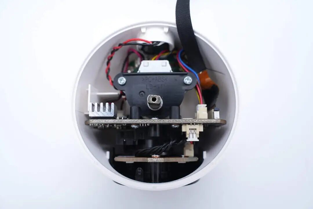
Inside the base, there is a stepper motor for horizontal rotation.
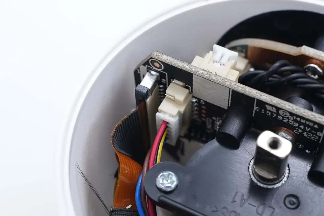
The connection ribbon cable connects through a socket.
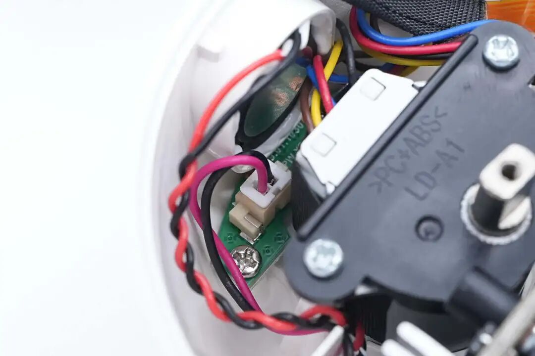
The USB-C interface small board connects through a socket.
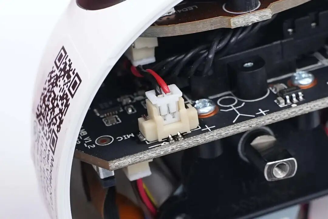
The microphone connects via a connector.
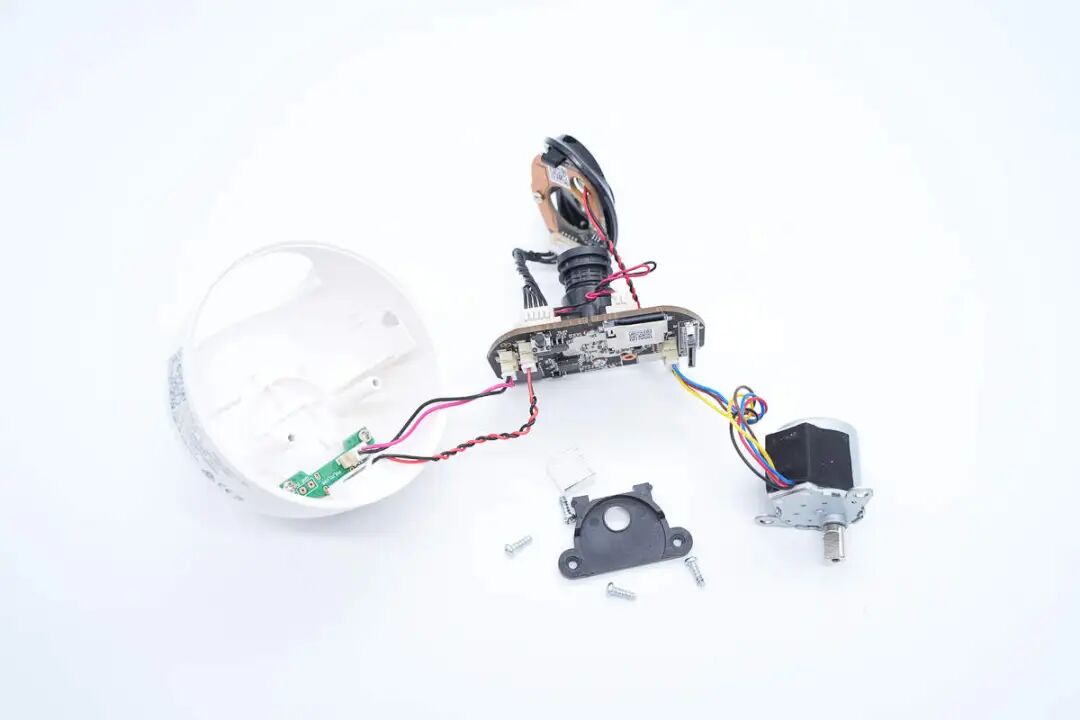
Remove the camera core and stepper motor from inside the base.
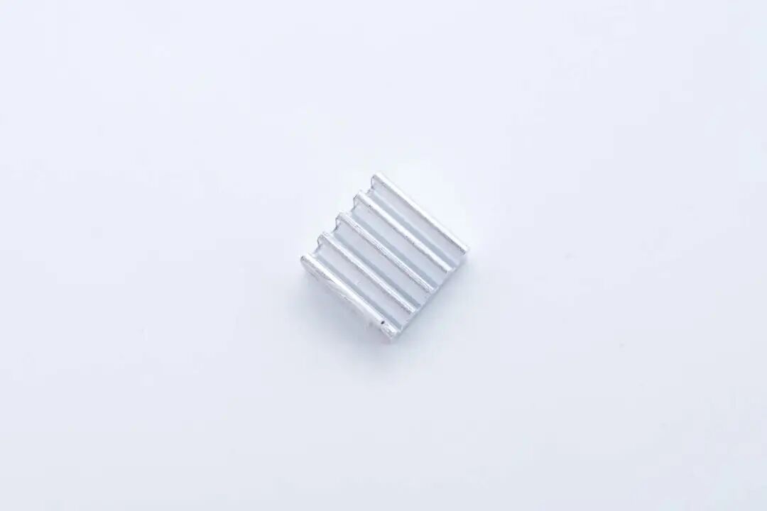
The main control chip is attached to the heat sink with thermal adhesive.
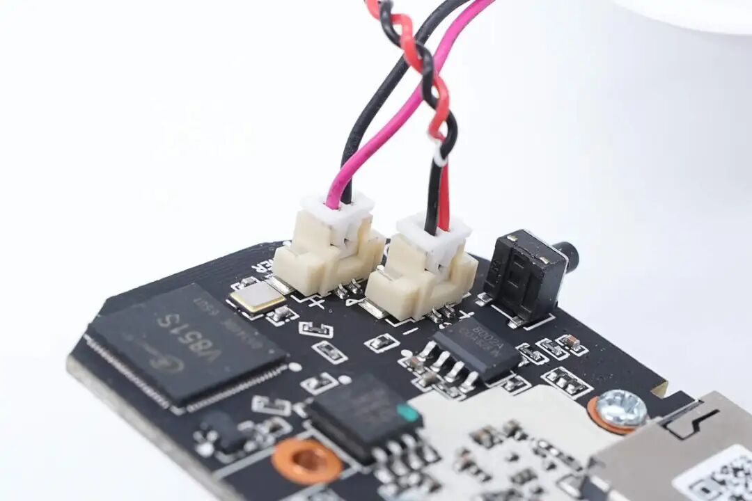
The speaker and power input connect via wires.
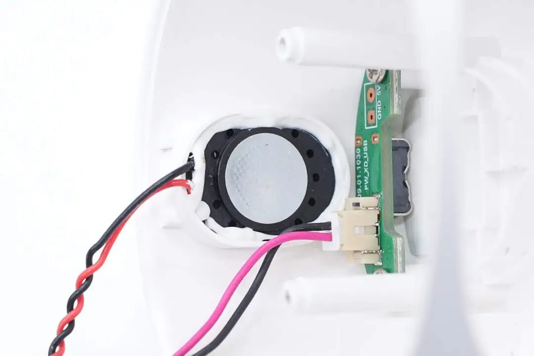
The wires connect to the speaker and the USB-C interface small board.
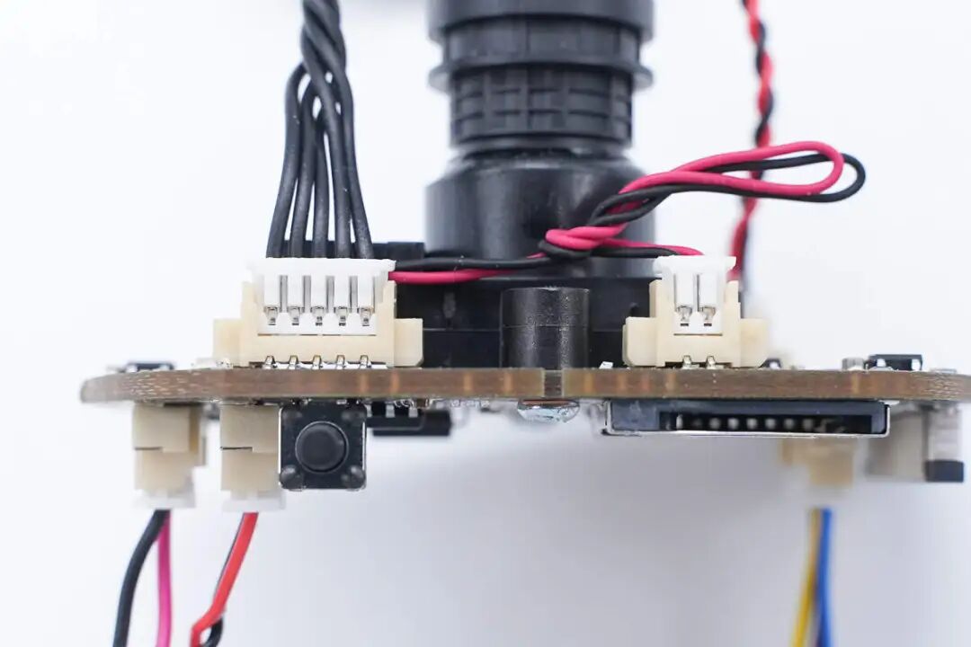
The ribbon cable is used to connect the fill light board and the filter switching coil.
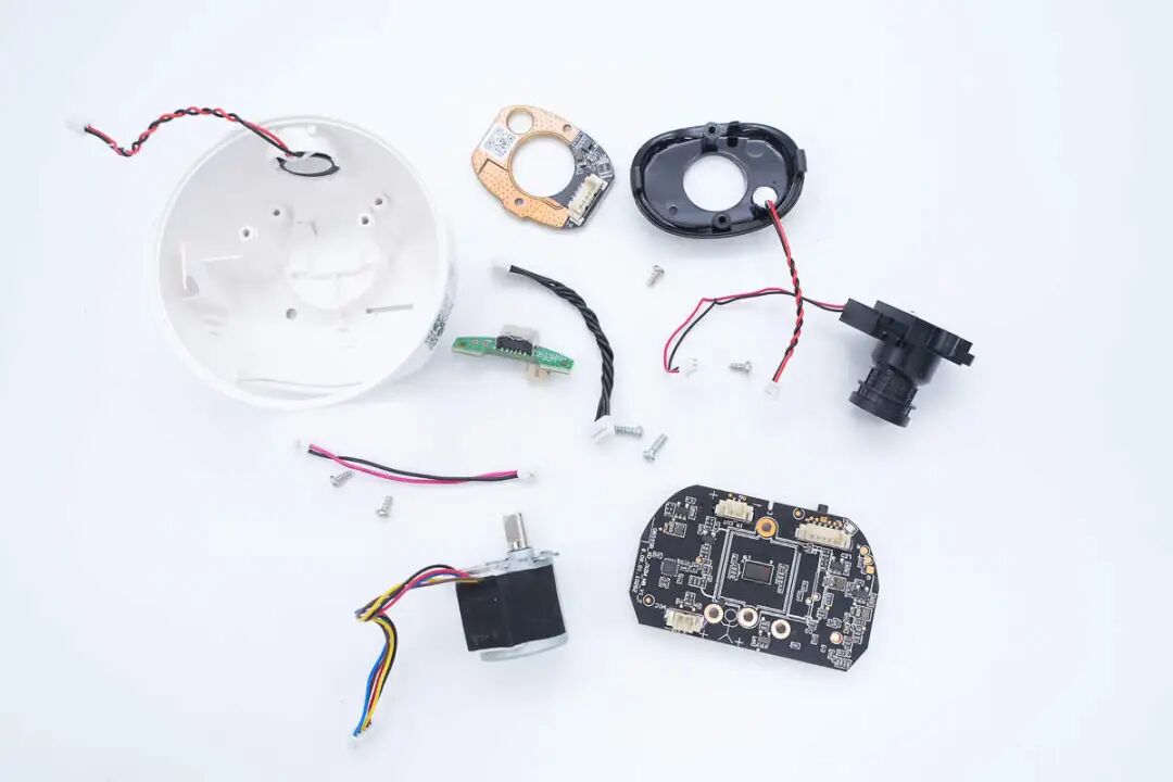
All components are removed from the casing.
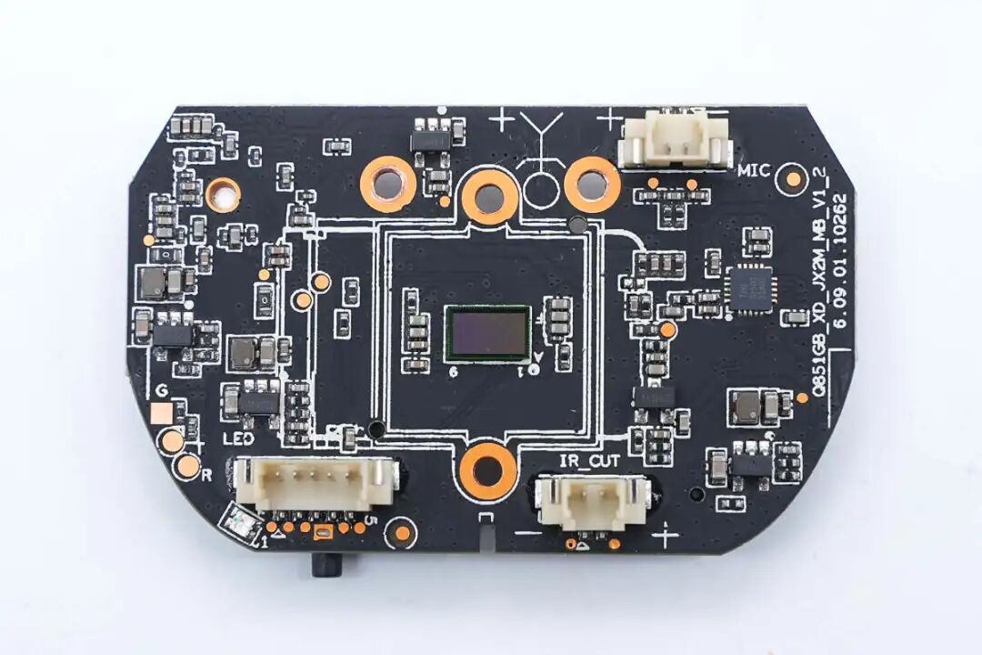
The PCBA module features a synchronous buck converter, motor driver chip, image sensor, and connectors on the front.
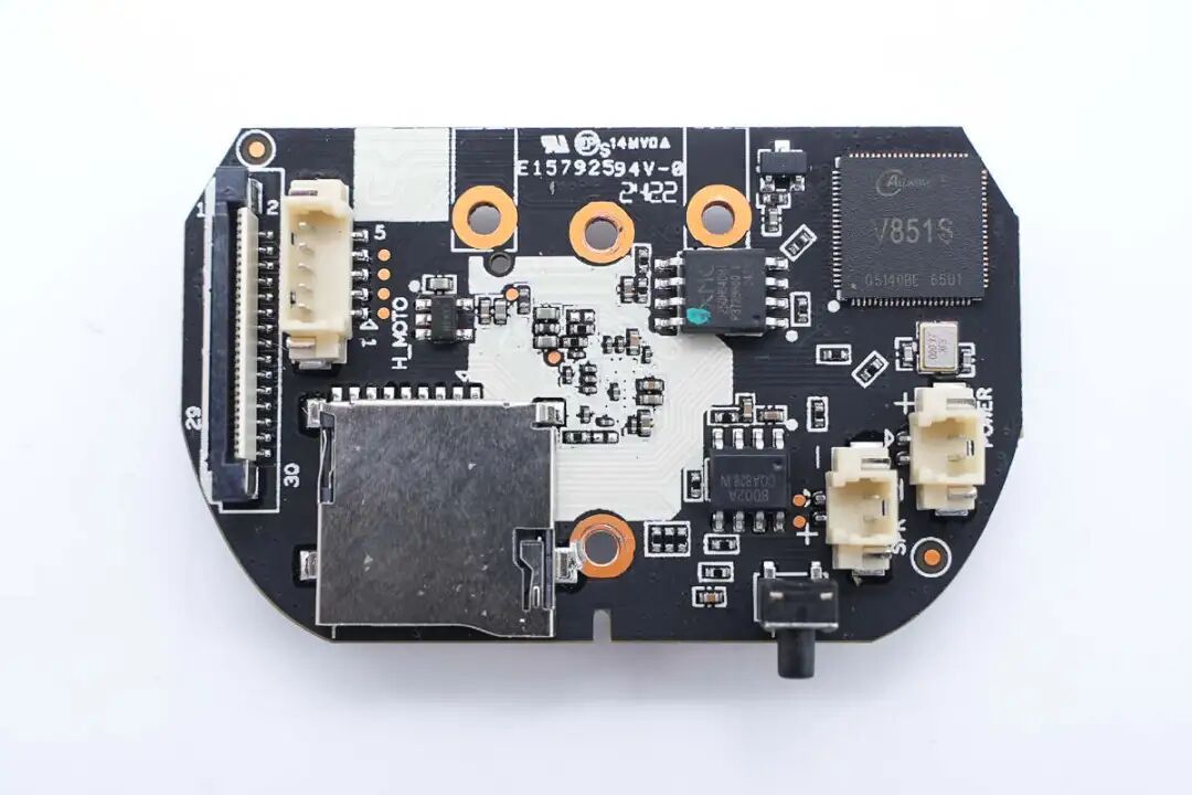
The back of the PCBA module features connectors, a TF card slot, the main control chip, memory, and an amplifier chip.
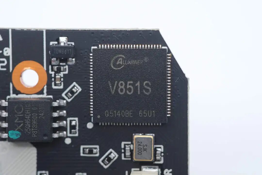
The main control chip of the camera is from ALLWINNER, model V851S, which supports dual camera applications, integrates an ARM Cortex-A7 CPU with a frequency of 900MHz, and includes a 600MHz RISC-V core, 64MB DDR2 memory, SMHC interface, SPI interface, and USB2.0 interface, packaged in QFN88.
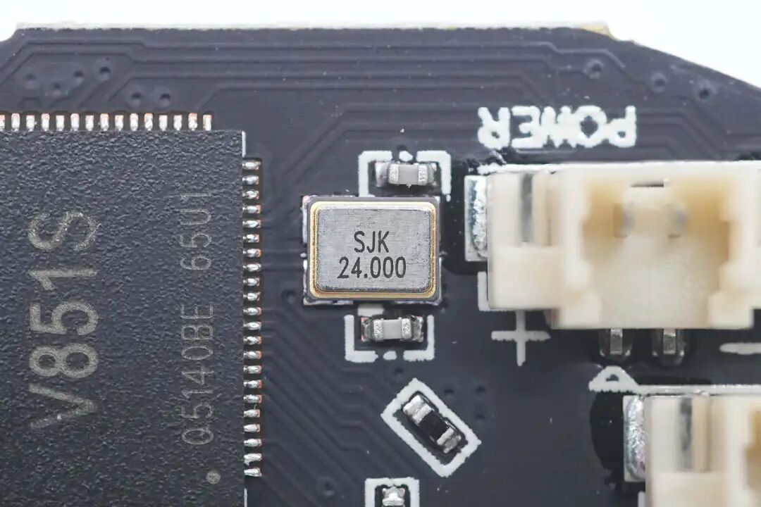
Close-up of the 24.000MHz clock crystal oscillator.
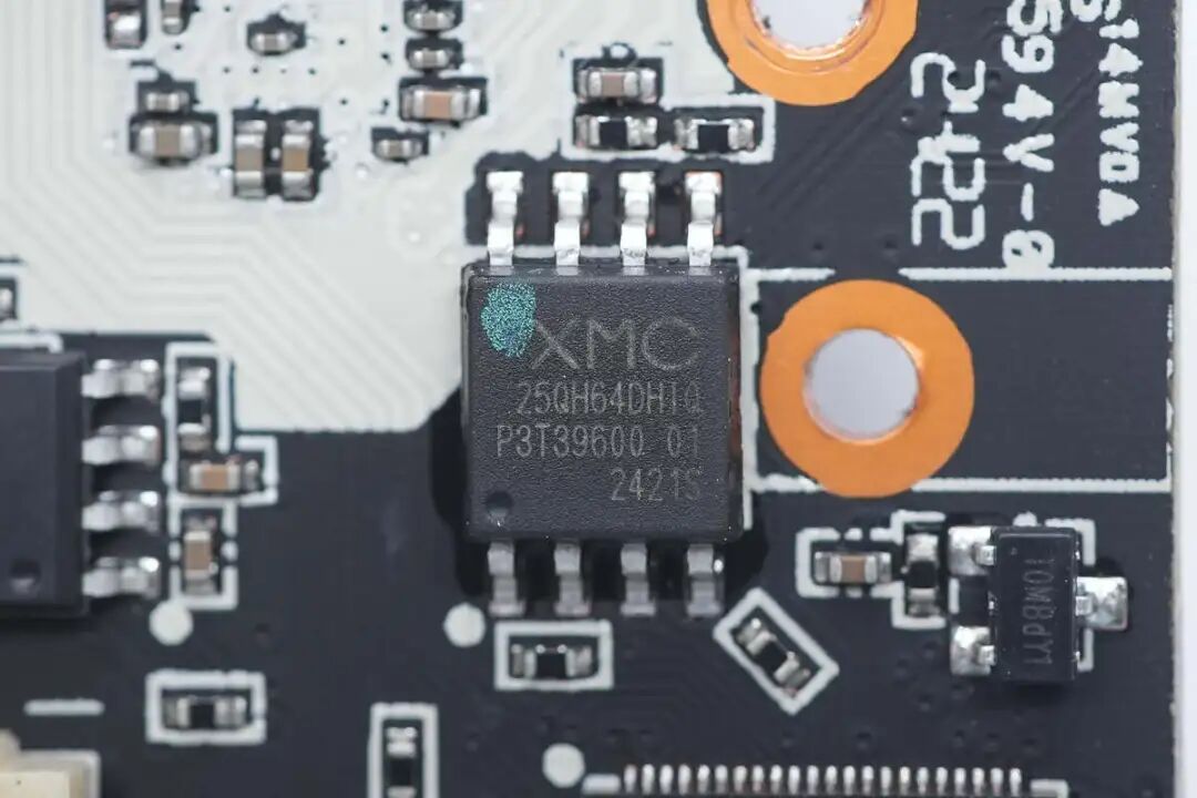
The memory is from XMC Wuhan Xinxin, model XM25QH64DHIQ, with a capacity of 8MB, packaged in SOP8.
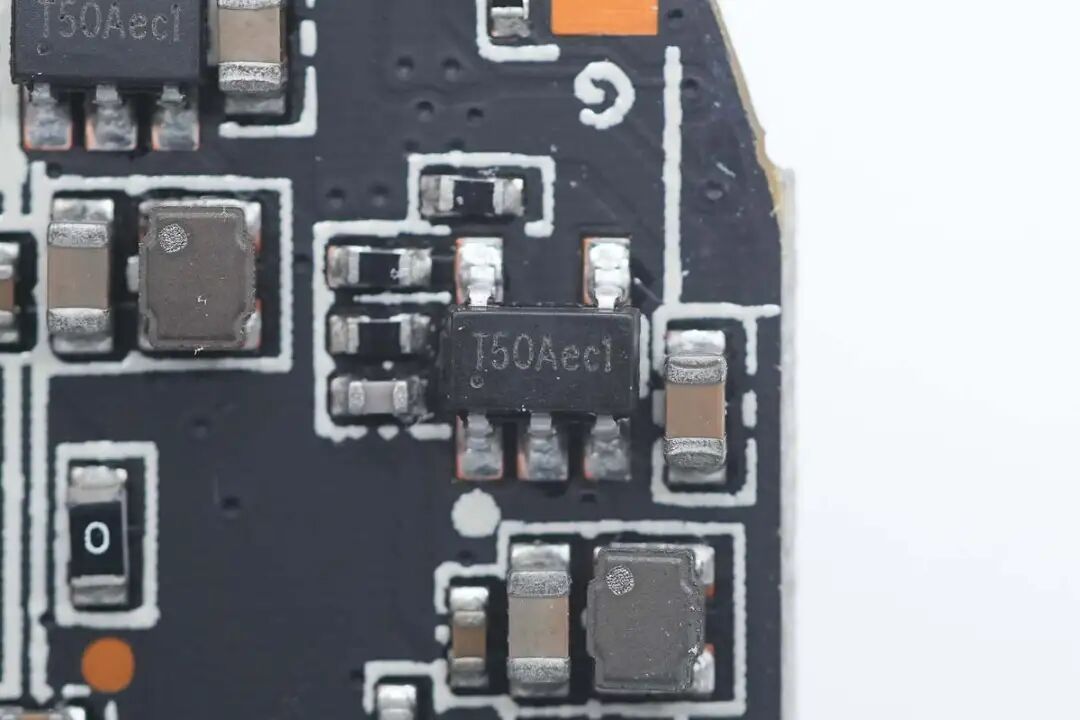
The synchronous buck chip is from Toread Micro, marked T50A, model TMI3108, which is a synchronous buck converter with a 5.5V input voltage, 1A output current, and a switching frequency of 1.5MHz, featuring excellent linear regulation and transient load response, packaged in SOT23-5.
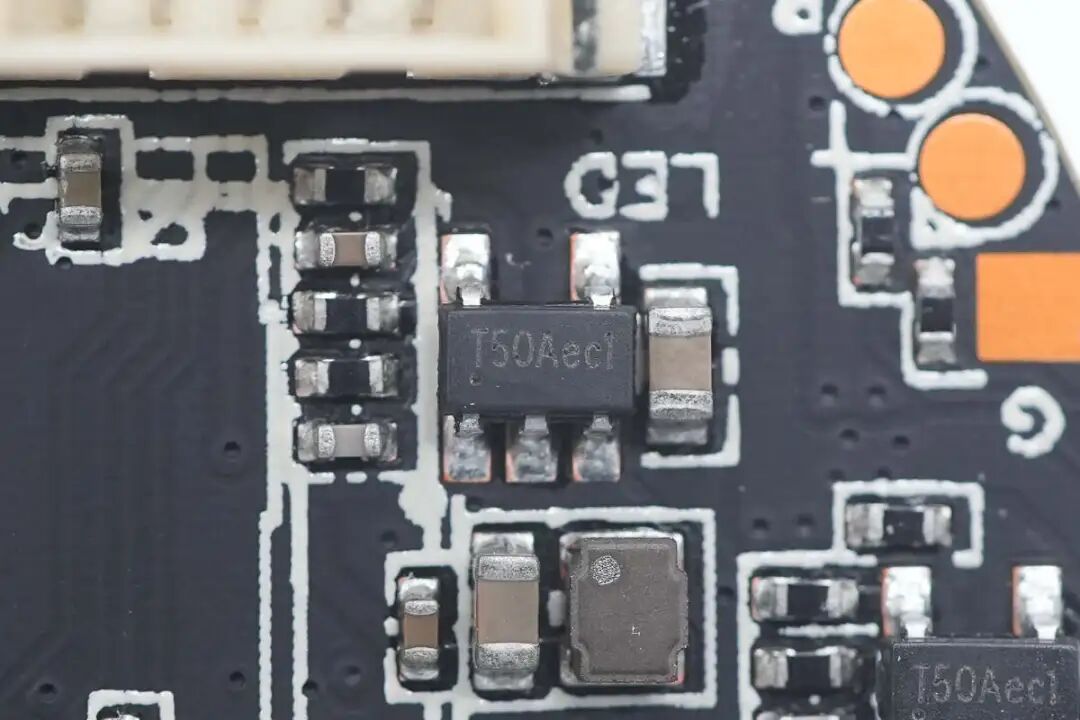
Another Toread TMI3108 synchronous buck converter close-up.
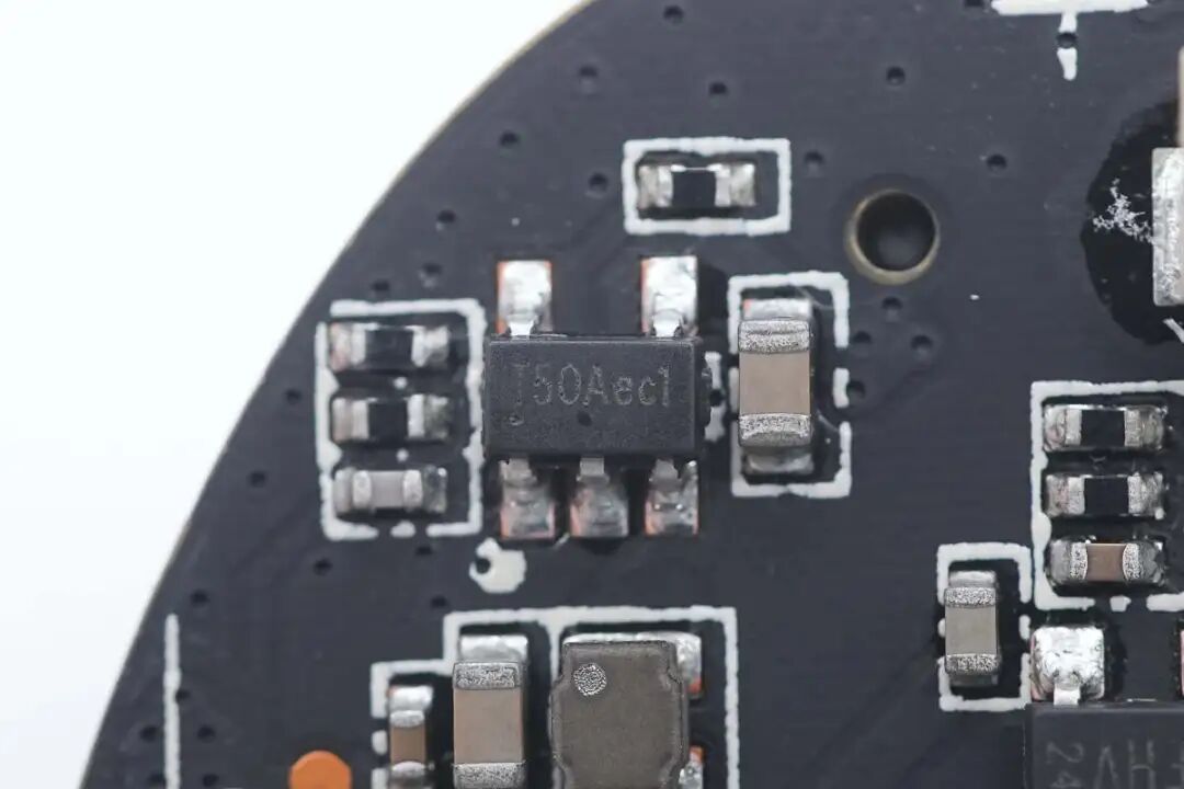
There are three TMI3108 chips used to supply power to the main control chip.
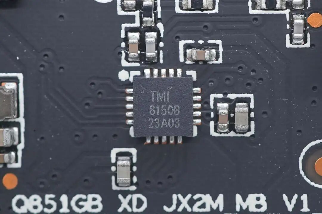
The motor driver chip is from Toread Micro, model TMI8150B, which has five driving channels, supports dual stepper motor driving and filter driving. The chip operates at a voltage of 2.4~5.5V, with a maximum continuous output current of 0.7A, and features a low-power sleep mode, packaged in QFN20.
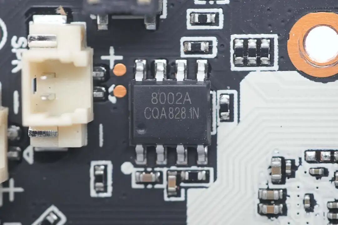
The amplifier for driving the speaker is marked 8002A.
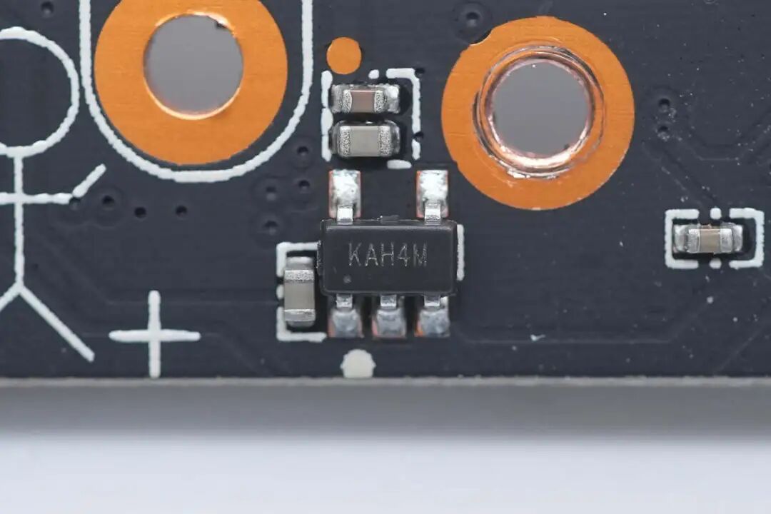
Close-up of the voltage regulator chip marked KAH4M.
Close-up of the voltage regulator chip marked KAK4H.
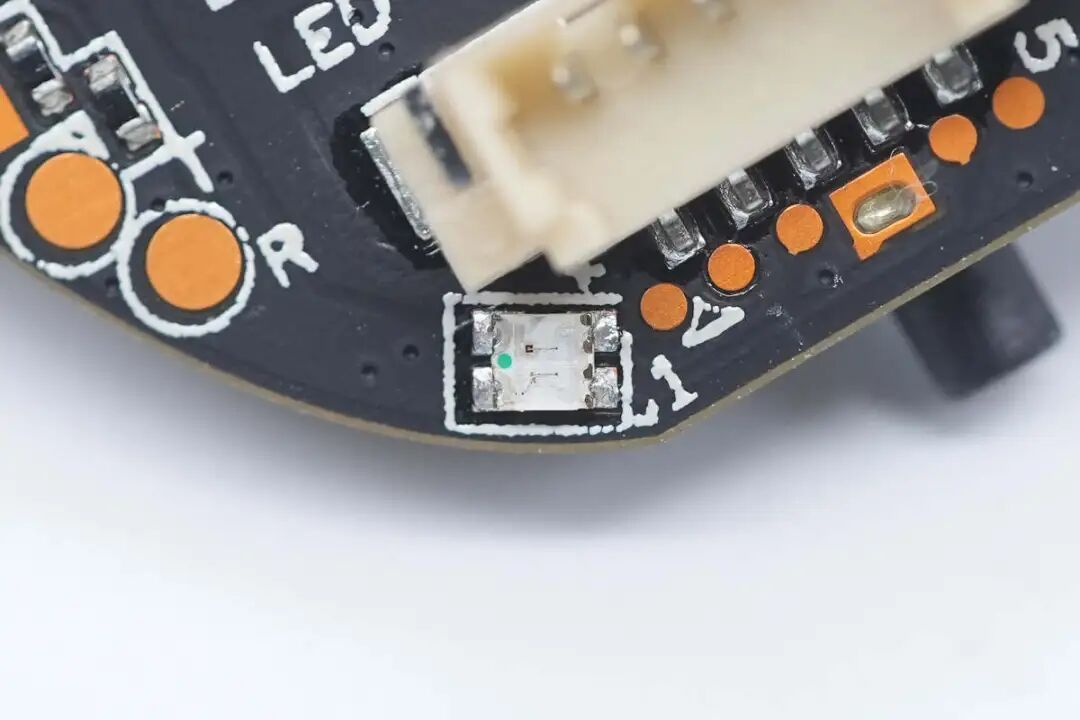
Close-up of the indicator light used to indicate operational status.
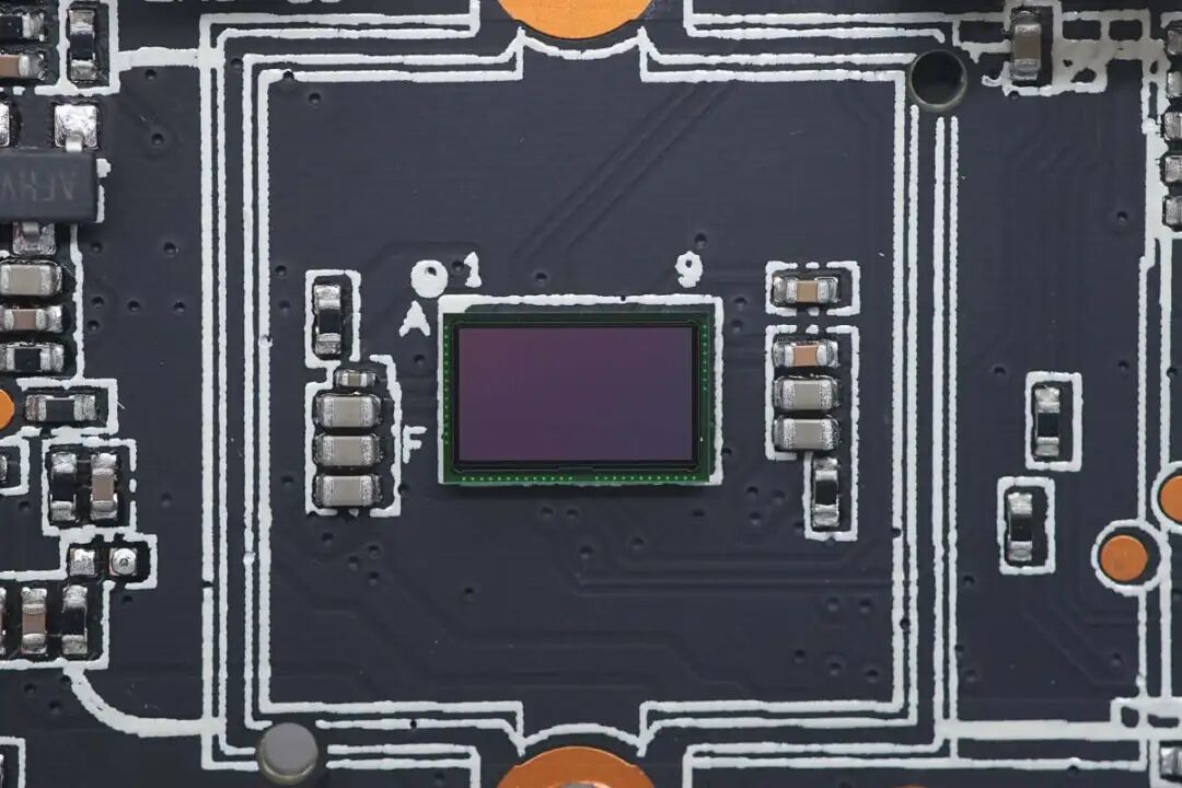
The image sensor chip uses CSP packaging.
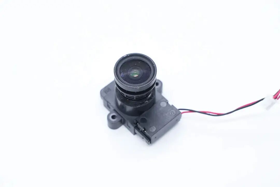
Close-up of the camera lens on the base.
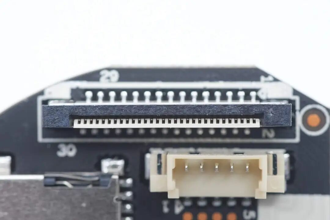
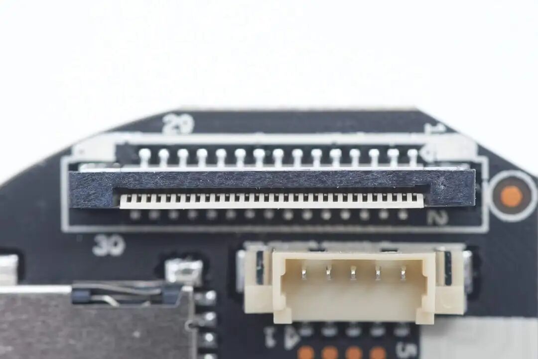
Close-up of the connector for the ribbon cable connecting the gimbal to the body.
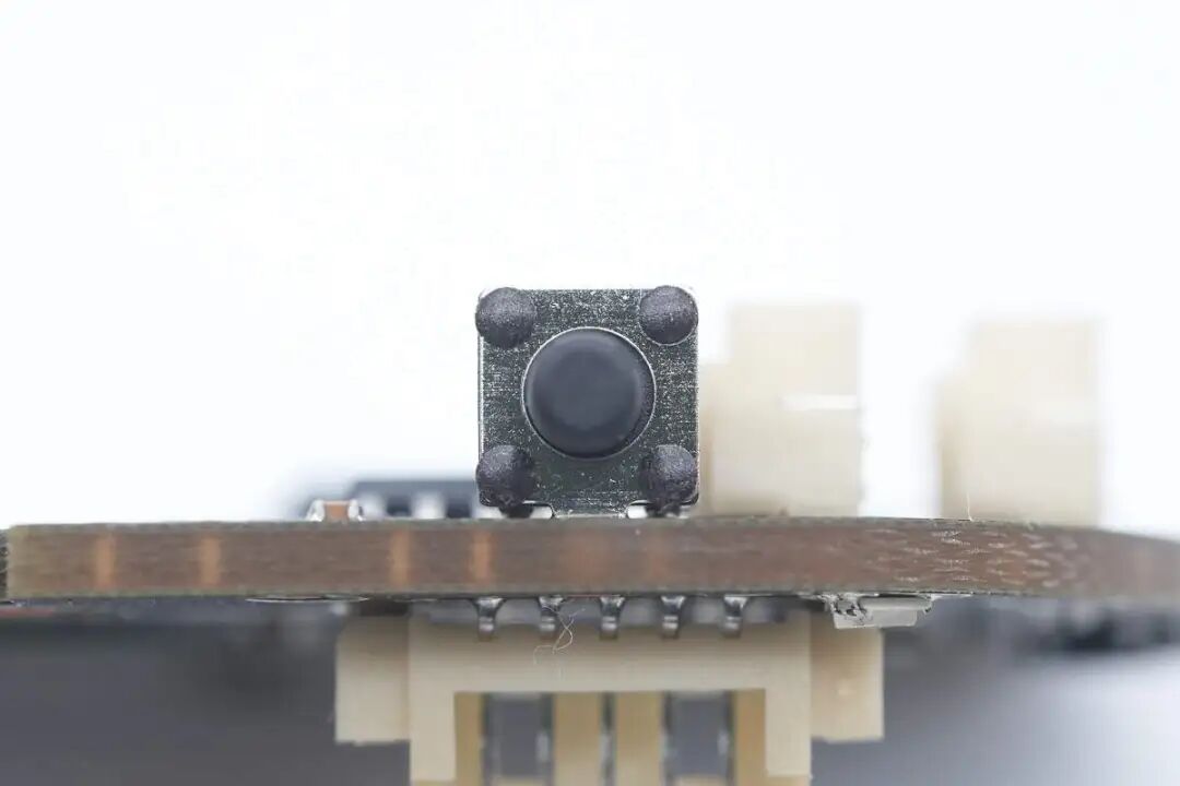
Close-up of the reset button.
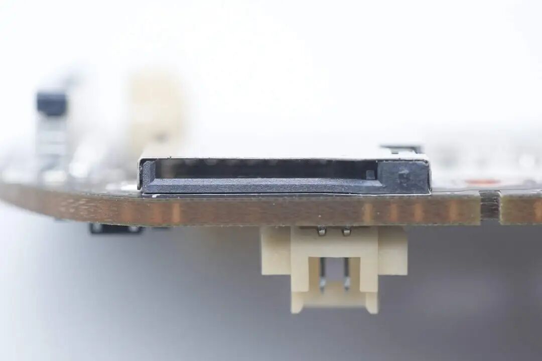
The TF card slot is soldered using surface mount technology.
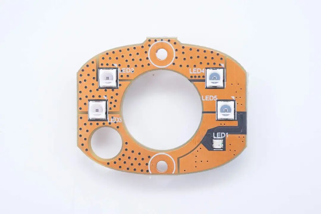
The fill light board is soldered with four infrared LEDs and an operational indicator light on the front.
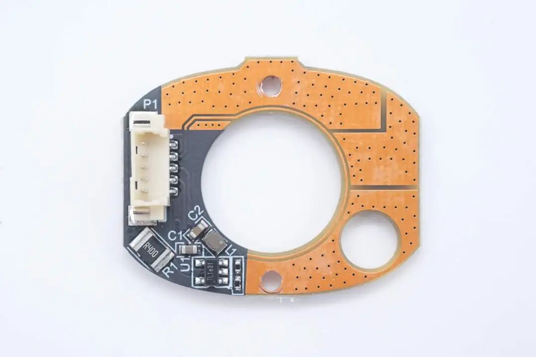
The back is soldered with connectors, buck chips, and other components, with large areas of exposed copper on both sides of the PCB to enhance heat dissipation.
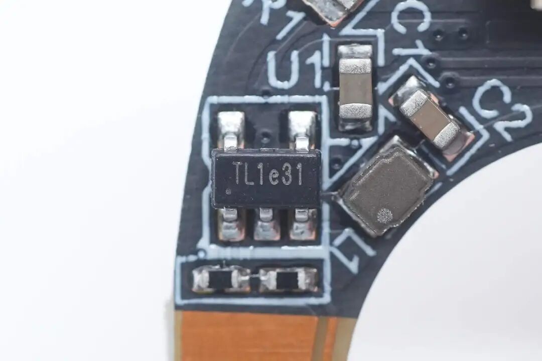
The driver chip for the infrared fill light comes from Toread Micro, marked TL1, model TMI5101, which is a synchronous buck architecture, internally integrating a switch tube, with a switching frequency of 1.5MHz, supporting 1A output current, 100% duty cycle output, and features short-circuit protection and overheat protection, packaged in SOT23-5.
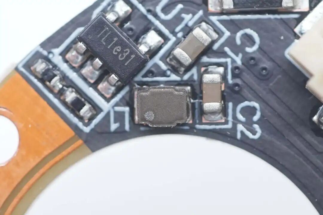
Close-up of the buck inductor used in conjunction.
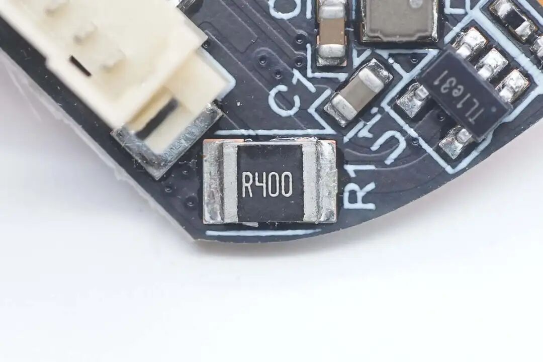
The 400mΩ sampling resistor is used for LED current feedback.
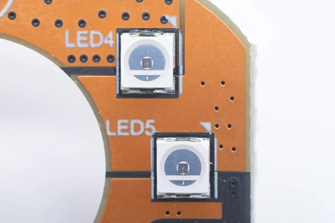
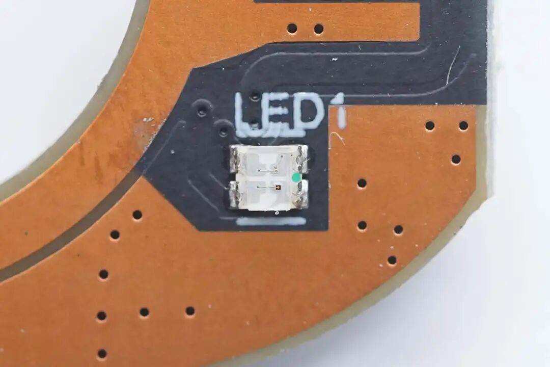
Close-up of the infrared fill light.
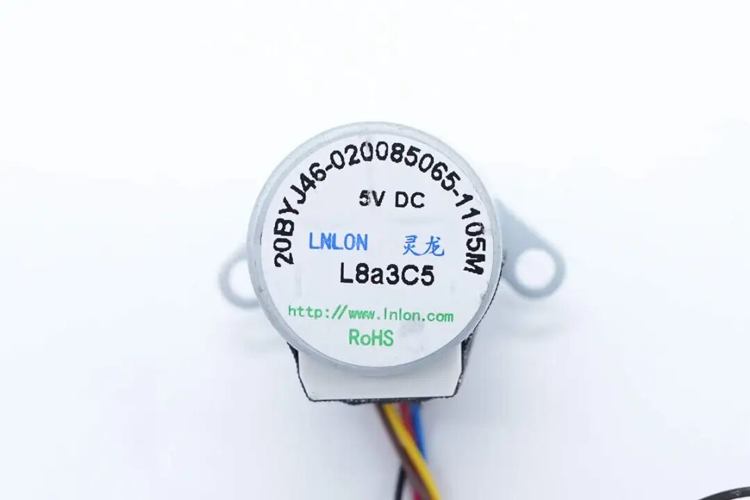
The stepper motor used for horizontal movement of the gimbal comes from LNLON.
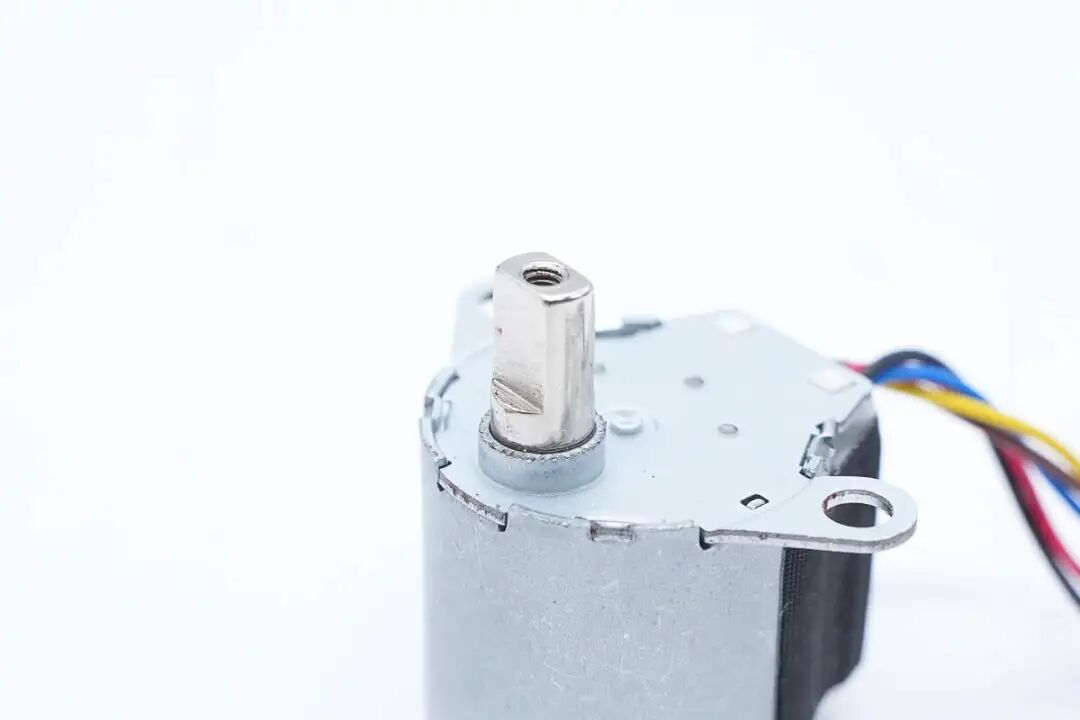
The motor features a metal output shaft.
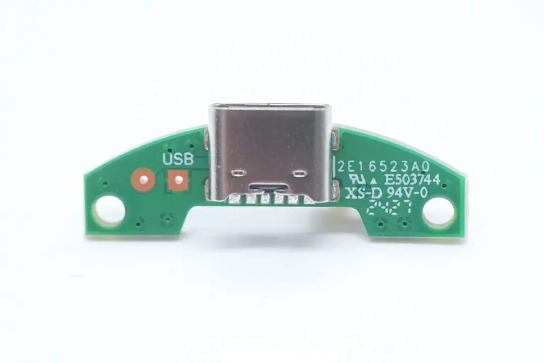
The power supply small board is soldered with a USB-C female connector.
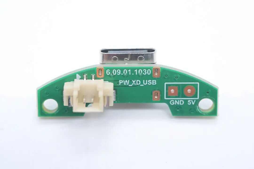
The other side is soldered with a power supply socket.
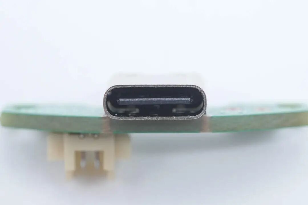
The USB-C female connector is fixed with through-hole soldering, with the black tongue not exposing copper.
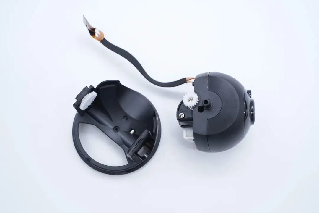
Next, disassemble the upper gimbal part.
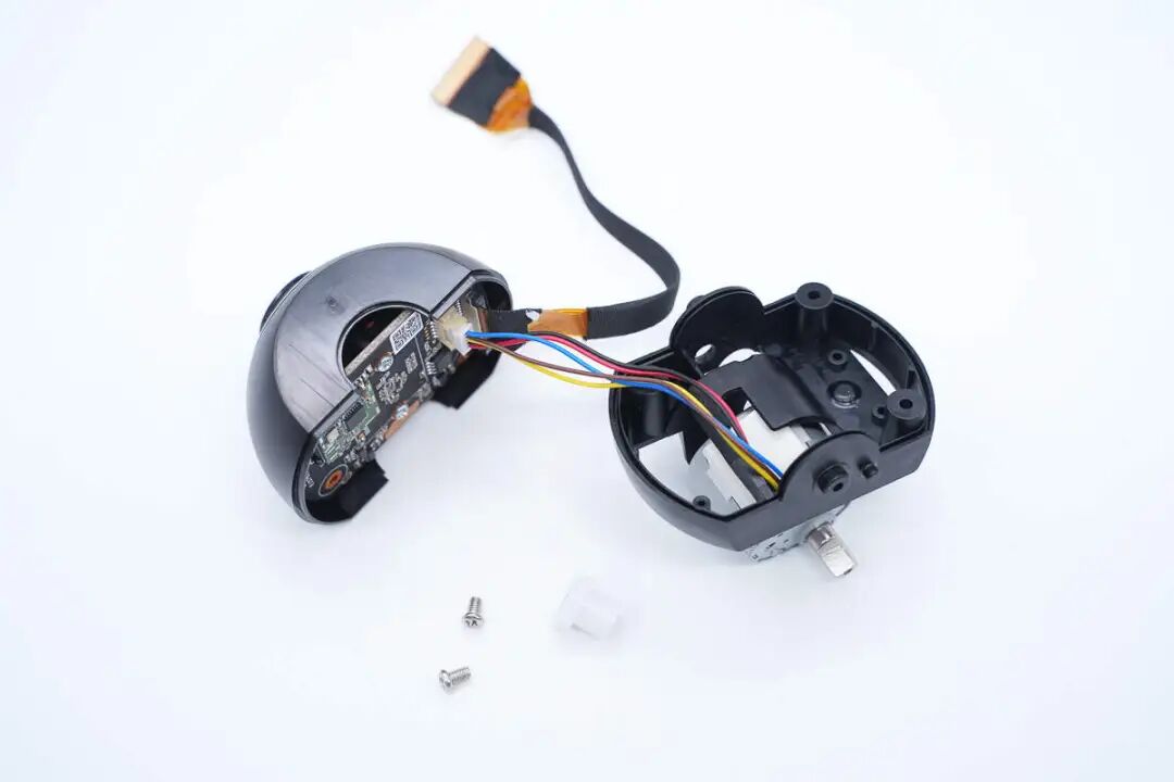
The gimbal shell is secured with screws.
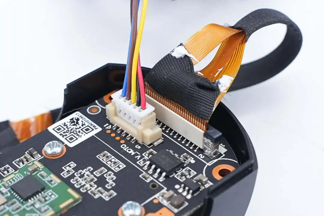
The stepper motor and connection ribbon cable are both secured with connectors.
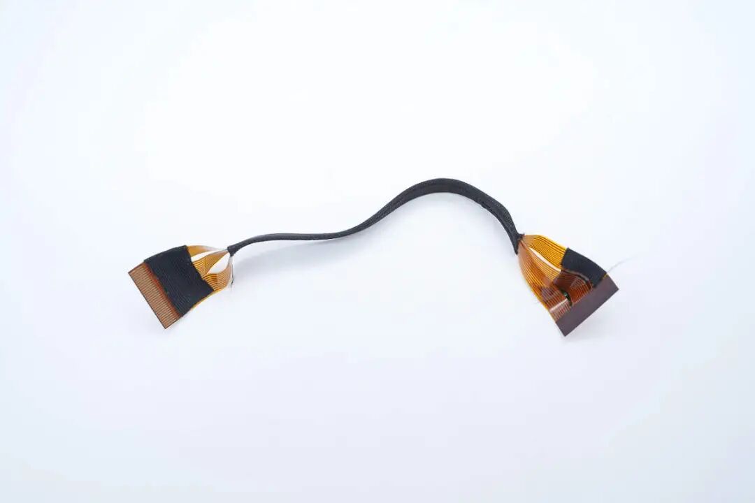
Close-up of the ribbon cable connecting the gimbal to the base.
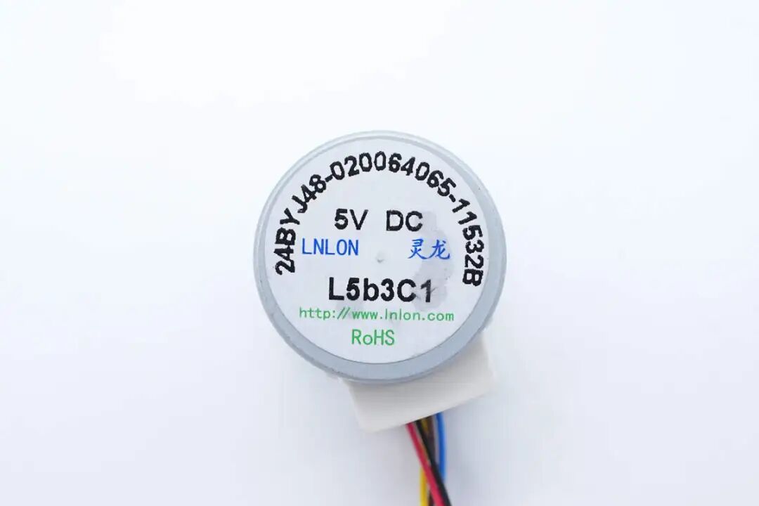
The stepper motor used for vertical movement of the gimbal comes from LNLON.
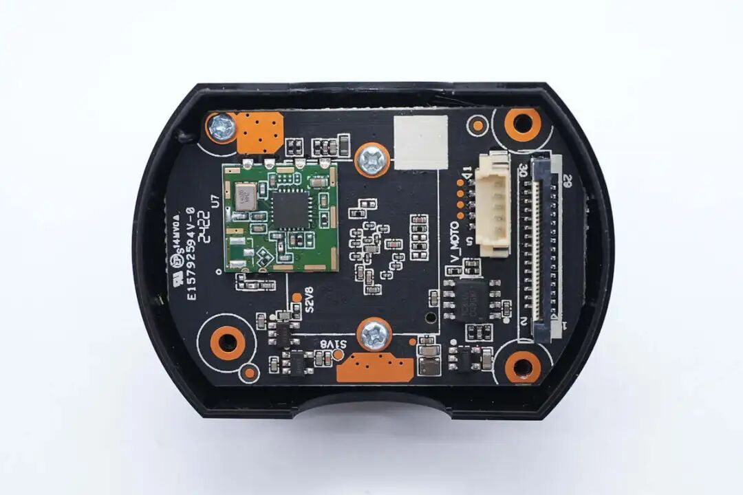
The PCBA module is secured with screws.
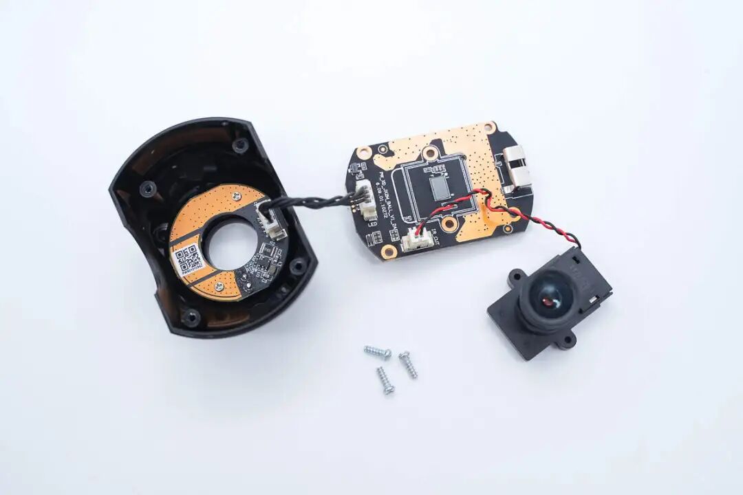
Unscrew the fixed screws to remove the internal PCBA module.
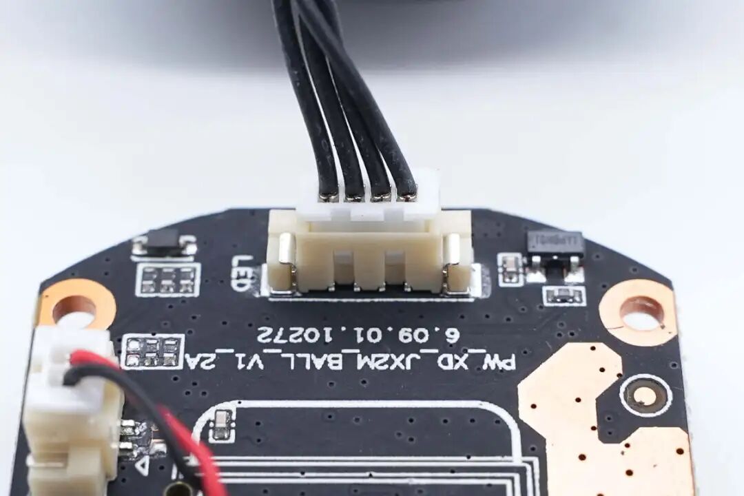
The fill light board connects via a connector.
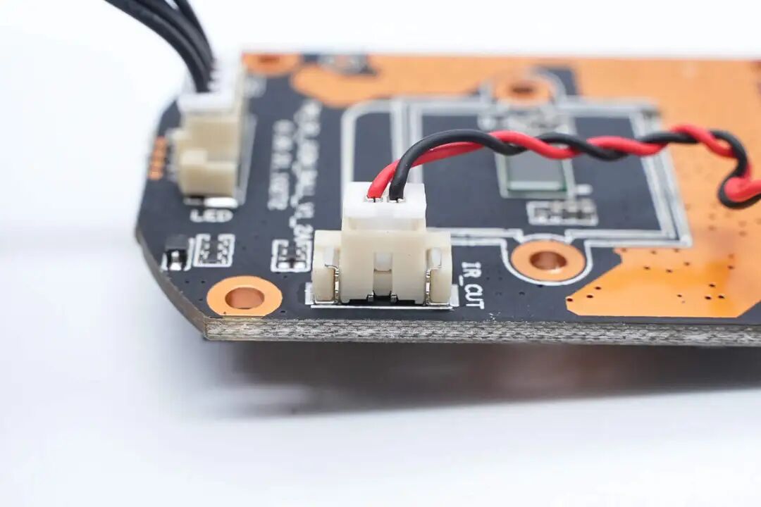
The filter switching coil is also connected via a connector.
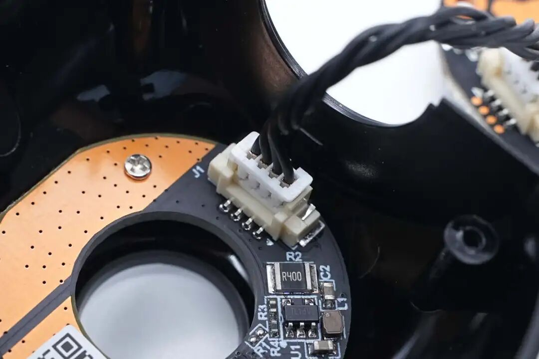
Close-up of the connection cable for the fill light board.
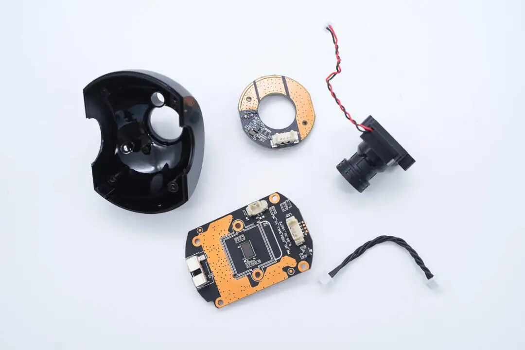
Remove the fill light board and camera sensor board from inside the casing.
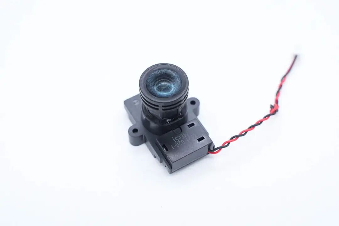
Close-up of the gimbal camera lens.
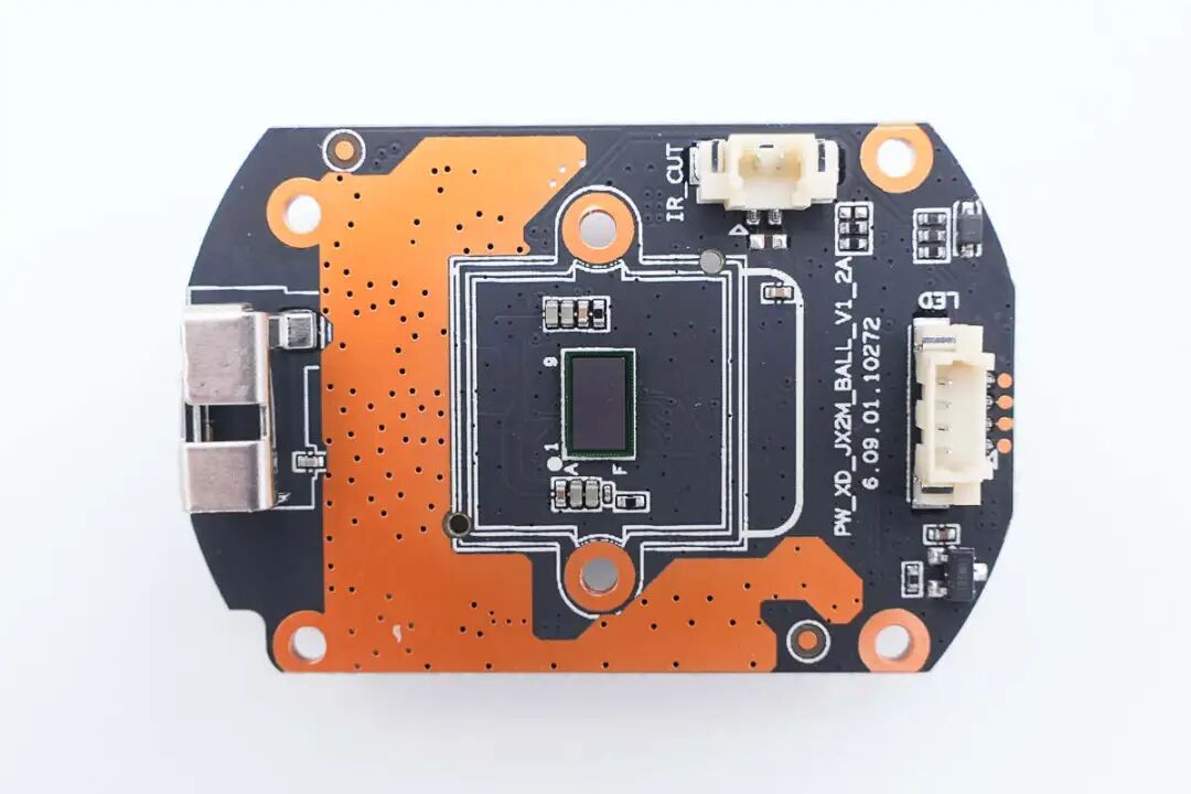
The front of the camera mainboard features a WiFi antenna, sensor, and connectors, with a Hall chip soldered in the lower right corner for detecting vertical position.
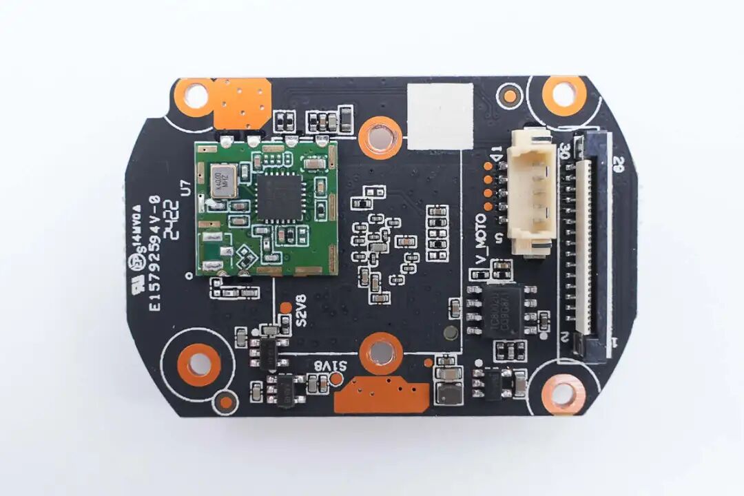
The back is soldered with a wireless transmission module, voltage regulator chip, synchronous buck chip, and amplifier chip, as well as connectors for the stepper motor and base.
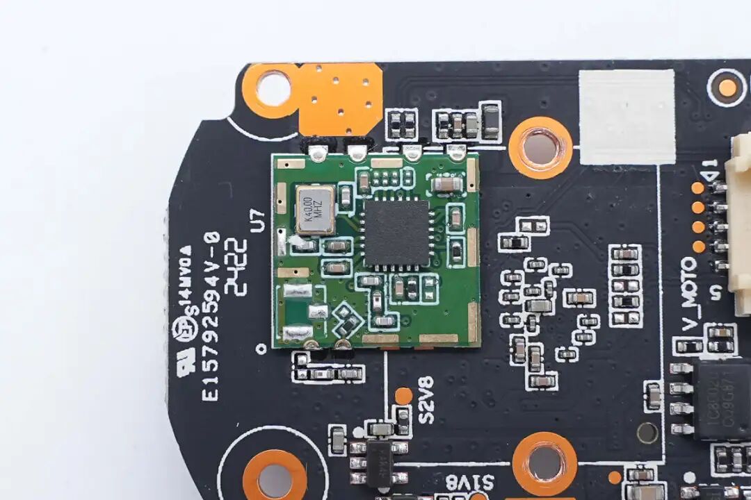
The wireless transmission small board is soldered using surface mount technology.
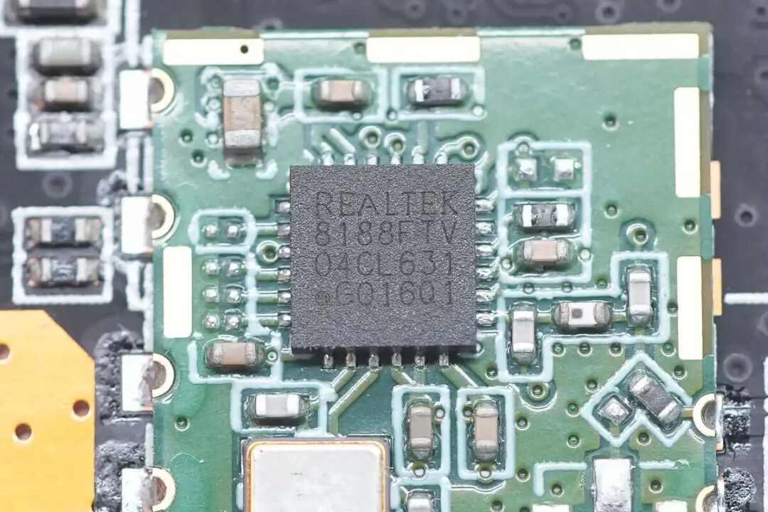
The wireless transmission chip comes from REALTEK, model RTL8188FTV, used for connecting the camera to the wireless network, supporting 802.11b/g/n wireless, packaged in QFN-24.
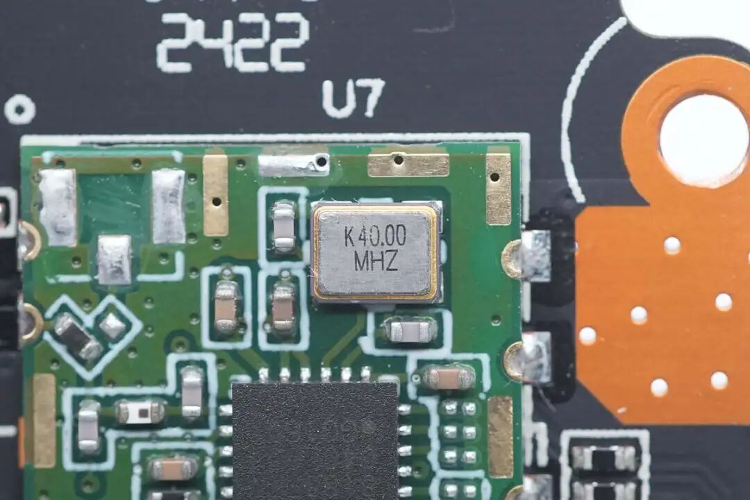
Close-up of the external 40.000MHz clock crystal oscillator.
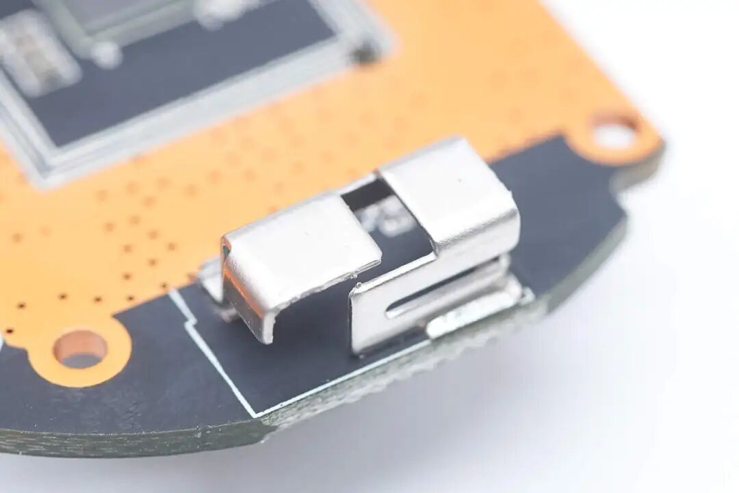
Close-up of the surface mount WiFi antenna.
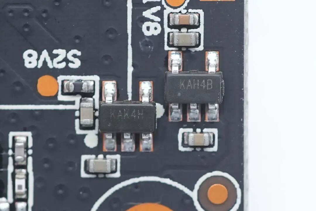
Two voltage regulator chips marked KAK4H and KAH4B, used for 2.8V and 1.8V output respectively.
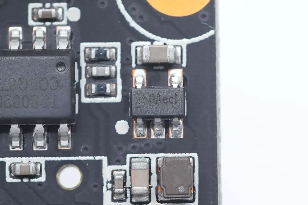
The synchronous buck chip is from Toread Micro, model TMI3108.
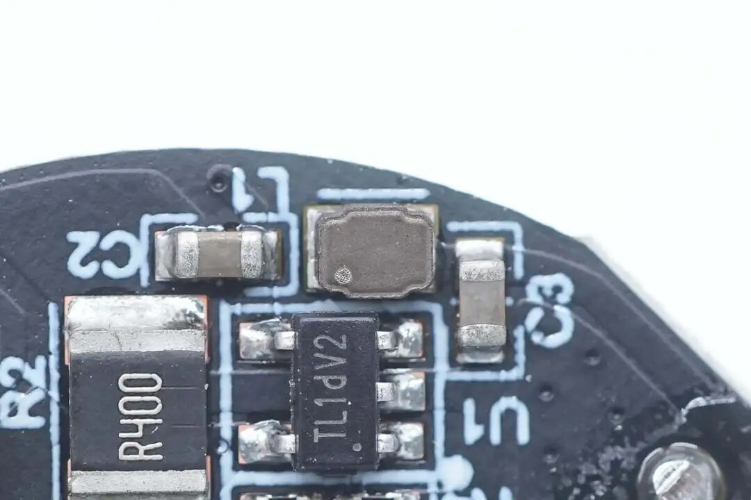
Close-up of the buck inductor used in conjunction.
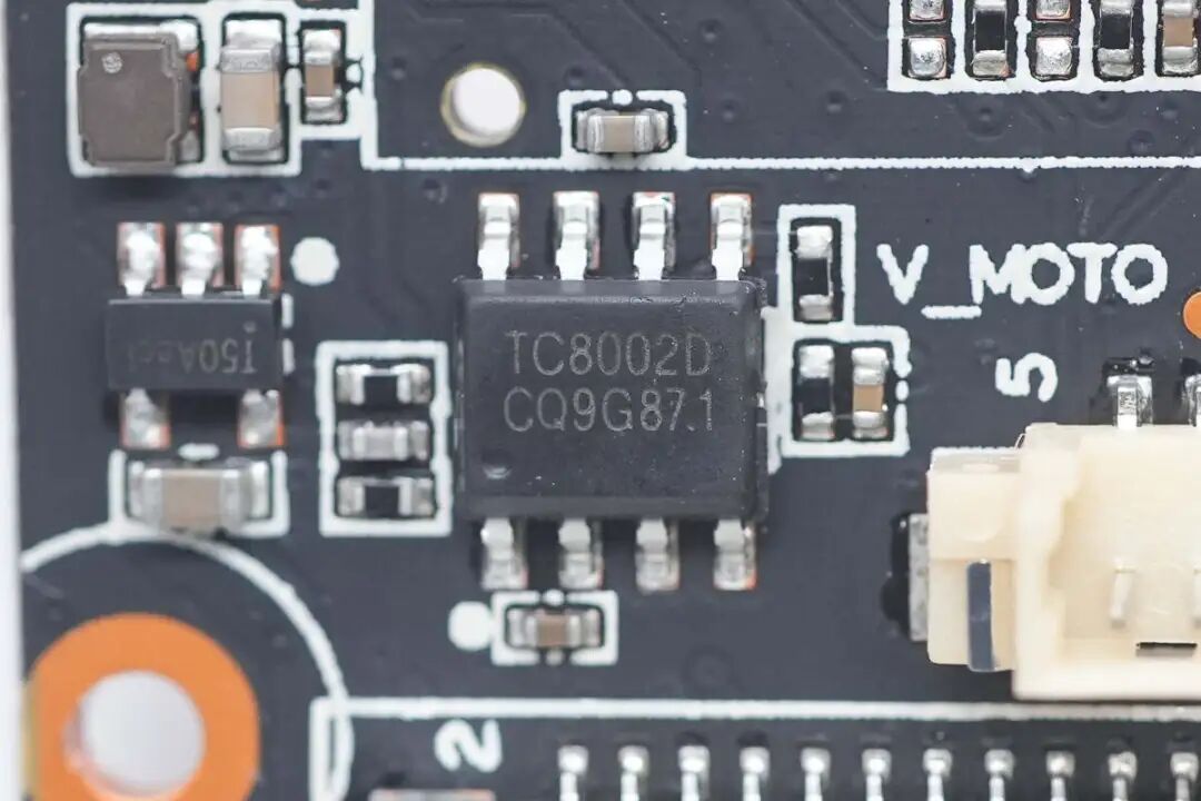
The speaker amplifier is marked TC8002D.
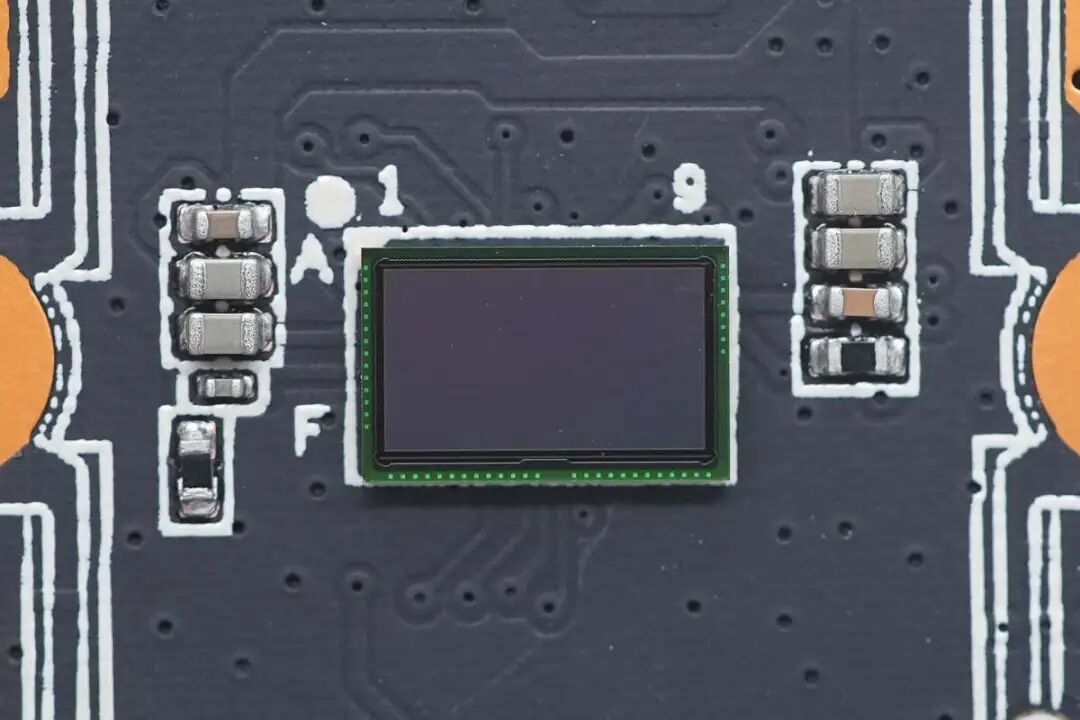
Close-up of the image sensor, which uses CSP packaging.
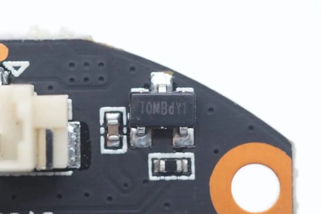
The Hall sensor comes from Toread Micro, model TMI86880MBS, used for detecting the vertical position of the gimbal, packaged in SOT23-3.
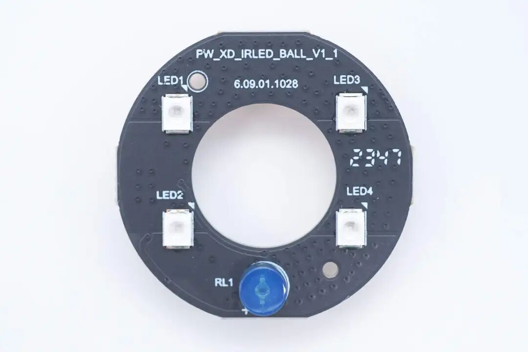
Close-up of the infrared fill light board, soldered with surface mount infrared LEDs and a light-sensitive resistor on the front.
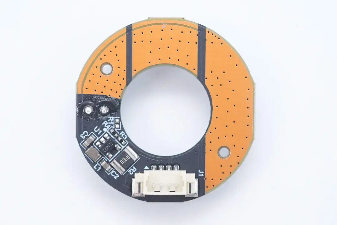
The back is soldered with the buck driver circuit.
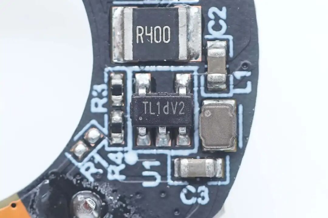
The synchronous buck chip comes from Toread Micro, model TMI5101.
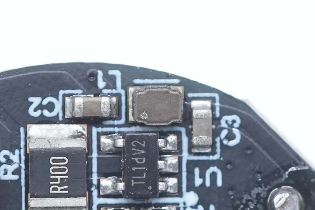
Close-up of the buck inductor used in conjunction.
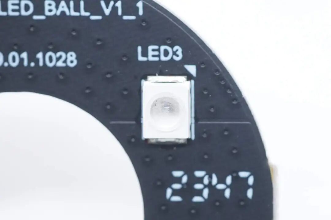
The surface mount infrared LED light close-up.
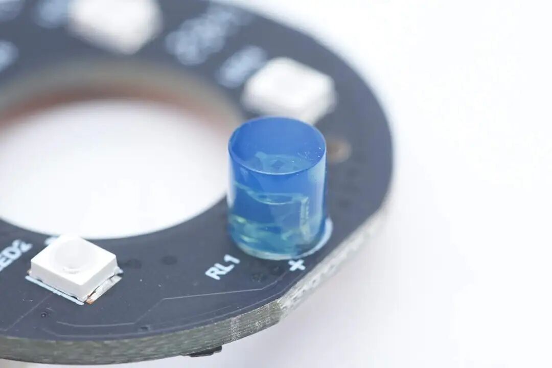
Close-up of the light-sensitive resistor used to detect ambient light intensity.
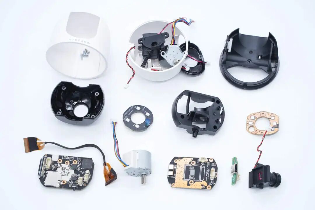
Overview of all disassembled components, a family photo.
Security Testing Room Disassembly Summary
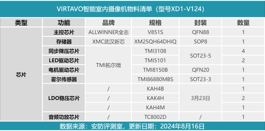
Finally, here is a list of core components of the VIRTAVO smart indoor camera for your reference.
The VIRTAVO smart indoor camera is equipped with two 4-megapixel lenses, designed with a gimbal + fixed lens configuration. The gimbal lens provides 360° monitoring without blind spots, capable of addressing security needs in two different areas simultaneously. The camera supports three modes: infrared/full-color night vision/off, catering to both home and commercial needs.
The Security Testing Room has learned through disassembly that this camera uses the ALLWINNER V851S main control chip, paired with Wuhan Xinxin memory. The switching buck chip, motor driver chip, and LED driver chip all come from Toread Micro. The gimbal is driven by a stepper motor, connected to the base via a ribbon cable, and the gimbal contains a wireless module for WiFi connectivity. The base houses a microphone and speaker for two-way intercom functionality.