In the previous two sections, we discussed the CANopen protocol stack PDO configuration for the robotic arm and established the spatial coordinate system and model of the robotic arm based on the improved D-H model. This section will simulate and test the robotic arm based on the above content and summarize the entire research.
4 Robotic Arm Control System Experiment
Sections 2 and 3 of this article introduced the CANopen protocol PDO configuration for motor control and the inverse solution process for the robotic arm from Cartesian space to joint space. The former provides a foundation for controlling joint motors, while the latter provides a theoretical basis for the robotic arm to achieve complex trajectory motion. Thus, the control process of the robotic arm system based on CANopen can be divided into: configuration of the CAN bus, input of the end target position, inverse kinematics solution for the robotic arm, sending joint angle commands, joint state feedback, and real-time feedback of the end pose from the visual end.
This article continues to focus on the end target pose M=[-0.275-0.582-0.455 0 π/2 0] as the research object, using the fifth group of inverse solutions to compare the target posture of the robotic arm under simulation and actual operation, and the choice of solution group will not be discussed here. (a) The figure shows the posture of the robotic arm’s end reaching point M in the matlab simulation, (b) shows the posture of the robotic arm’s end actually moving to point M. To ensure smooth operation of the joints during actual movement, a low-speed operation is adopted, setting each joint’s speed to 0.01 rad/s, and acceleration to 0.05 rad/s2. The control process of the robotic arm system is shown in Figure 5.
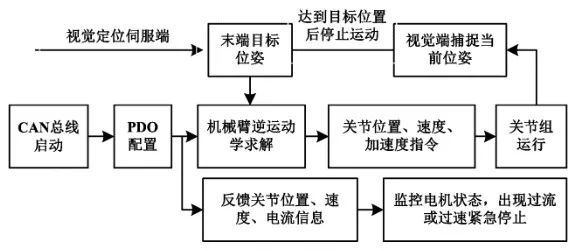
Figure 5 Robotic Arm Control System Process
By comparing the two images, it can be determined that the poses of the robotic arm are approximately the same. The above experiments verify the feasibility of the CANopen-based robotic arm control system, effectively enabling the robotic arm’s end to move to the specified spatial position. The comparison of target pose simulation and actual movement is shown in Figure 6.
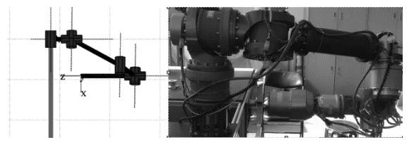
(a) Target Pose Simulation (b) Target Pose Actual Movement
Figure 6 Comparison of Target Pose Simulation and Actual Movement
5 Conclusion
This article studied a robotic arm control system based on the CANopen protocol. The research achieved point-to-point movement of the robotic arm’s end in the CAN bus, providing a practical foundation for the robotic arm to achieve complex spatial trajectory motion. The introduction of the CAN bus simplifies the system structure and improves system stability, while the standardization of the CANopen protocol enables the design of a universal robotic arm controller.
The main issues in this research include: the existence of multiple solutions in the robotic arm’s inverse kinematics, requiring further research on solution selection; and how to achieve trajectory planning for the robotic arm in Cartesian space, enabling obstacle-avoidance movement at the arm’s end. These issues will be the direction of the author’s future research.
(Original article reprinted from: “Research on CANopen-Based Robotic Arm Control System”, authors: Wang Yaonan, Gao Xiaolong, School of Electrical and Information Engineering, Hunan University)