1. Introduction
In response to the complex wiring, single control, and low reliability issues of servo motor remote control, a new method for controlling servo motors using the CANopen communication protocol and the drive sub-protocol is proposed. This article analyzes the object dictionary and message format of the CANopen protocol, detailing the transitions of each step in the CANopen servo control state machine and the message settings for the three servo control modes: PP, PV, and HM under the CANopen protocol. An experimental platform was established using a CAN card, servo drive devices, and a PC, successfully implementing the control of the servo motor in the PP, PV, and HM modes based on the CANopen protocol through message settings on the host computer interface. The experimental results show that controlling the motor using message settings from the protocol is simple and easy to operate, with fast and reliable communication data, allowing users to effectively monitor the servo motor through the host computer.
2. Overall System Architecture
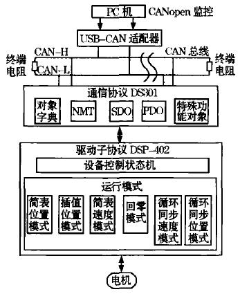
The entire control system consists of a PC, a CANopen host computer, a USBCAN adapter, and servo drive devices. The CANopen communication part is implemented using the DS301 protocol, while the servo control part is implemented using the DSP402 protocol.
The servo drive device acts as a slave node with CANopen communication capabilities, responsible for controlling the motor’s current, speed, position, and other control objects. It connects to the bus via a communication interface and transmits information to the host computer interface; the host computer interface controls the servo drive device through the USBCAN adapter based on feedback information from the slave.
The overall architecture of the servo control system is shown in the figure.
3. CANopen Servo Control Principle
1) CANopen Communication Device Model
The CANopen device model is divided into three parts: communication unit, object dictionary, and application process. Users can describe devices with completely different functions through this model.
The core concept of CANopen is the object dictionary, which contains all parameters describing the device and its network behavior. Both the application unit and communication unit can query this parameter list. Parameters in the object dictionary are identified and located through a 16-bit index and a sub-index.
The communication part consists of CAN transceivers, CAN controllers, and the CANopen protocol stack. The protocol stack defines the communication objects for implementing communication: NMT (Network Management Message), PDO (Process Data), SDO (Service Data Object), predefined messages, or special functional objects (including synchronization messages, emergency messages, time stamp objects, etc.). All content and functions of communication are described by these communication objects, and communication between all devices is also completed through these communication objects. Among them, NMT is used for the master to manage the status of the slave and for the slave to respond with its communication status, SDO is used for the master to configure and monitor the object dictionary of the slave. PDO is used to transmit high-speed, small data. Special functional objects are used for synchronizing communication objects in the network (usually PDO).
The application part defines and describes the basic functions of the device, serving as a link between the device and the master host computer. Its core function is to configure parameters, control states, and monitor the device by accessing the object dictionary, and to transmit process data information of the device at high speed.
2) Servo Control Modes
The CANopen drive and motion control device sub-protocol DSP402 has very precise requirements for the description of characteristics; it not only defines the operating modes of the driver but also defines the state machine used to control the driver.
The driver state machine is controlled through the control word 6040 in the object dictionary and reads the driver’s status through the status word 6041. The control state machine is shown in the figure.
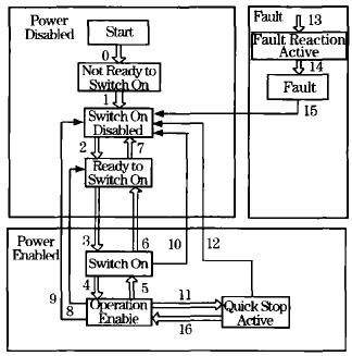
The state machine can be divided into three parts: “Power Disabled” (main power off), “Power Enabled” (main power on), and “Fault”. All states enter the “Fault” state after an alarm occurs. After power-on, the driver completes initialization and then enters the SWITCH_ON_DISABLED state. In this state, CAN communication can be performed, and the driver can be configured. The main power is still off, and the motor is not excited. After State Transition 2, 3, and 4, it enters the OPERATION ENABLED state, at which point the main power is on, and the driver controls the motor according to the configured operating mode. State Transition 9 completes the shutdown of the main power circuit. Once the driver experiences an alarm, its status enters FAULT.
The PP mode (Position Mode) is a typical positioning mode that can control the motor to run to the target position through single-step and continuous setting methods. The PV mode (Speed Mode) is the speed control mode, and HM (Homing Mode) provides various methods to reach the starting position.
4. System Hardware and Software Implementation
1) System Hardware Setup
This design uses a USBCAN adapter, servo drive devices, and a PC to set up the hardware platform. The servo drive control chip used is a DSP chip.
The system hardware setup is carried out in the following steps. First, configure the relevant parameters in the TI development environment, and establish a DS301 project to complete the debugging and operation of the CANopen protocol communication program. After the project debugging is successful, it is downloaded to the driver, and message settings are made in the host computer interface to test SDO, PDO, NMT, and other communication objects. If the test results are correct, the system hardware setup is complete.
2) System Software Design
The entire software design for servo control is established in CCS and mainly includes the closed-loop control program for permanent magnet synchronous motors and the implementation of the CANopen protocol. The flowchart is shown in the figure.
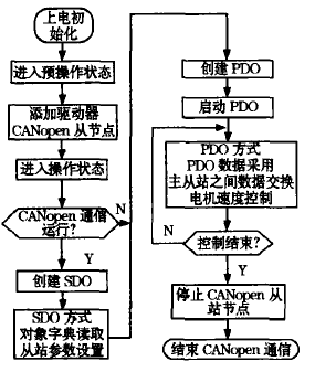
The initialization part of the program mainly completes the initialization of the DSP system and the initialization of CANopen communication.
The main tasks completed during initialization are as follows:
Initialize relevant variables, enable global interrupts, and read the three-phase signal from the servo motor encoder’s Hall sensor (UVW) to determine the motor’s initial electrical angle position.
The main tasks completed during communication initialization are as follows:
Set the slave node address and CAN communication baud rate, initialize each communication object, complete the predefined mapping of each channel, and finally enter the communication processing program.
3) Servo Control Message Settings
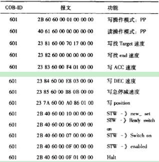
The CANopen message structure consists of an 11-bit COB-ID and a data field of up to 8 bytes. In the host computer interface, the NMT message is used to control the slave to enter the pre-operational state or operational state, and then the SDO message is used to set various parameters (speed, position, etc.) for servo control and the various states of the state machine, allowing the motor to operate according to different control modes. Finally, by mapping the current parameters of the motor to PDO, the values of the PDO message can be read to obtain the current values of the motor and compare them with the set values to determine the correctness of the control results. All control messages are implemented by SDO.
1. PP mode control message list, see the table.
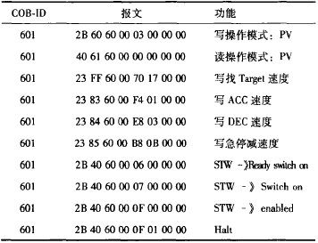
2. PV mode control message list
3. HM mode message list
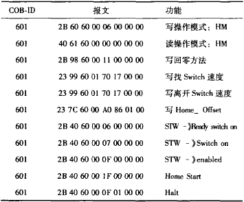
The operation of the three control modes messages first sets the servo control mode, then sequentially inputs the related target control values (such as position, speed, homing method, etc.) according to the current mode, and finally uses the 6040h control to start and stop the motor according to the state machine steps.
5. System Control Mode Verification
The host computer interface of this system consists of two parts: the USBCAN host computer interface and the motor monitoring interface, with the USBCAN host computer interface serving as the CANopen message data monitoring interface, and the motor monitoring interface developed in VB2008. In the host computer interface, the communication baud rate is set to 1 Mbps, the servo motor Node-ID is set to 1, the heartbeat cycle is 1s, and the TPDO sending cycle is 100ms. The parameters of the motor’s current loop, position loop, and speed loop are set, and the set messages are sequentially input into the SDO control of the host computer interface. The motor starts and runs to the set values in the messages, and the values displayed on the motor’s manual remote control are consistent with the set values. At the same time, the message display values in the host computer interface are also consistent with the set values, successfully achieving servo control.
1) The position control curve in the motor monitoring interface for PP mode.
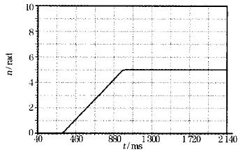
In the host computer interface, set the message values, and the motor starts. The motor first accelerates and runs, reaches the set target speed value, and then runs at a constant speed until it reaches the set target position value without further changes. The process data on the host computer is consistent with the changes in the motor monitoring curve. If there is a need to change the motor’s position value, new control messages can be sequentially input in the host computer interface, and the motor will rotate forward or backward according to the set values, continuing to run to the new position.
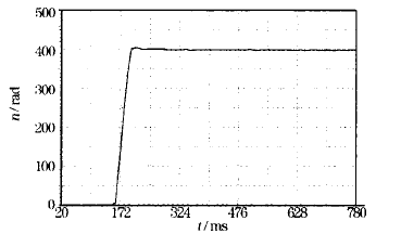
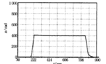
2) In PV mode, the motor first accelerates to the set target speed value and then runs according to the set value. If there is a need to change the running speed, new speed values can also be input in the host computer interface.
The changes during acceleration are as described above. During deceleration control, the motor decelerates until the speed stops. The data changes on the host computer are consistent with the changes in the motor monitoring curve.
The speed control curve is shown in the figure.
3) In HM mode, the motor first accelerates to the set speed and then searches for the origin position. After finding the origin, the motor returns to zero and decelerates until the operation is complete. At this time, both the host computer interface and the manual remote control of the servo motor can view the current position value of the motor, indicating that the motor’s zero return operation is complete. The position curve is shown in the figure.
6. Conclusion
Practice shows that the system operates reliably, data is accurate and easy to analyze, and the motor first accelerates, reaches the set target speed, and then begins to run at a constant speed with good real-time performance. The protocol stack program is easy to embed. This method can be extended to apply to multi-motor control systems, and the CANopen communication protocol stack is suitable for all devices, with very broad engineering applications.
The original article is reprinted from: “Control Engineering”
Authors: Yi Lingzhi, Chen Haiyan, Lu Qixiang, Wang Fangfang, School of Information Engineering, Xiangtan University