In the previous section, we introduced the system structure of the robotic arm and configured the CANopen protocol stack’s PDO. This section will discuss the mapping process of the robotic arm’s position from Cartesian space to joint space description based on the improved D-H model.
3 Inverse Kinematics Solution of the Robotic Arm
According to the improved D-H model, the coordinate system of the ARM-Robot robotic arm is established as shown in Figure 2, where the node numbers in the CAN network correspond to the joint coordinate numbers, and coordinate system 0 serves as the base coordinate system of the robotic arm.
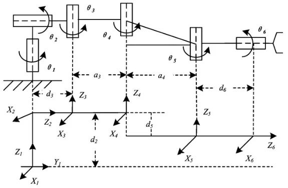
Figure 2 Robotic Arm Spatial Coordinates
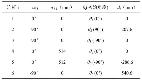
After establishing the coordinate system, the D-H parameters are determined according to the constraint relationships between adjacent coordinate systems. The D-H model, also known as the four-parameter method, defines αi as the angle of rotation around the Xi axis from Zi to Zi+1; αi is the distance moved along the Xi axis from Zi to Zi+1; θi is the angle of rotation around the Zi axis from Xi-1 to Xi, defined as the initial angle of the adjacent joint coordinate system; di is the distance moved along the Zi axis from Xi-1 to Xi. The D-H parameter table is shown in Table 3, where the range of θ is from -π to π.
Table 3 D-H Parameters
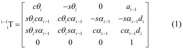
The transformation matrix of the coordinate system {i} relative to the coordinate system {i-1} is called the link transformation matrix. Here we directly use the expression from the introduction to robotics:
Substituting the link parameters from Table 3 into equation (1), we obtain the link transformation matrix for adjacent joints:
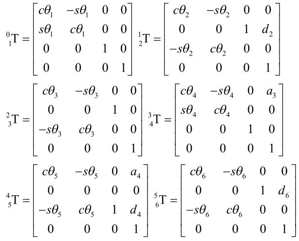
Where cθi = cosθi, sθi = sinθi. The transformation matrix of the robotic arm’s end effector relative to the base coordinate system can be expressed as

The visual positioning module of the robotic arm provides the target pose of the robotic arm’s end effector in Cartesian spaceM=[x y z α β θ], where x, y, z are the spatial poses of the target point relative to the base coordinate, and α, β, θ are the attitude angles of the target point relative to the base coordinate. Given the pose and attitude angles of the robotic arm’s end effector relative to the base coordinate system, the attitude angle transformation matrix of coordinate system {6} relative to the base coordinate system can also be described using Euler angles. We adopt the Z-Y-X Euler angle method, where the three rotations are around the Z, Y, and X. It is expressed as follows:
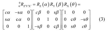
Then the Euler angle representation is
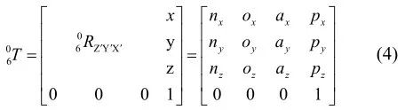
Using equations (2) and (4), we can obtain the angles of each joint θi (the specific calculation process is omitted due to space limitations):
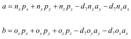
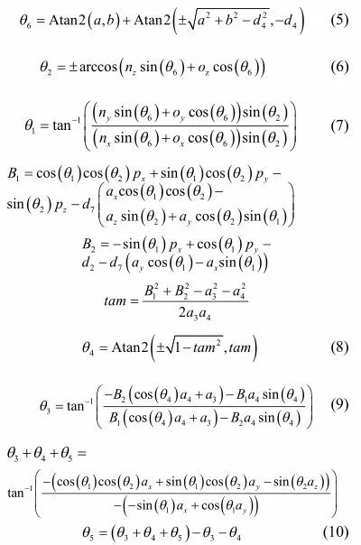
Equations (5)-(10) provide the solutions for θ1 – θ6, and the inverse solution for the robotic arm’s 6 joint angles yields a total of 8 sets of solutions. This complies with the inverse kinematics solvability theory for a 6R robotic arm with three consecutive joint axes parallel proposed by Duffy. We use the MATLAB roboticstoolbox for MATLAB toolbox to verify the correctness of the above inverse solution for the robotic arm’s joint angles. The robotic arm model is established in MATLAB, with its initial configuration shown in Figure 3.
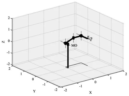
Figure 3 Robotic Arm Model
The target pose M=[-0.275 -0.582 -0.455 0 π/2 0] is taken as an example, where x, y, z are in meters, and α, β, θ are in radians. Using the above joint calculation formulas, we obtain 8 sets of solutions, as shown in Table 4, with joint angles in radians.
Table 4 Joint Inverse Solutions
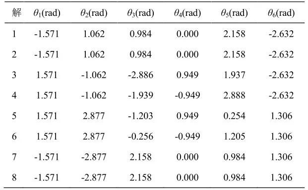
By inputting the obtained joint angles into the MATLAB robotic arm model, the end effector’s position matches the target pose M, verifying the feasibility of the above algorithm. The verification diagram for the fifth set of solutions is shown in Figure 4.
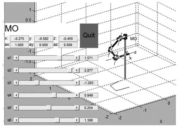
Figure 4 The End Pose of the 5th Set of Inverse Solutions
For the subsequent content, please pay attention to the next update on the WeChat public account.
(Original text reproduced from: “Research on CANopen-Based Robotic Arm Control System”, authors: Wang Yaonan, Gao Xiaolong, School of Electrical and Information Engineering, Hunan University)