CANopen is a high-level communication protocol built on the Controller Area Network (CAN), including communication sub-protocols and device sub-protocols commonly used in embedded systems, and is a widely used fieldbus in industrial control. CANopen implements protocols above the network layer in the OSI model (including the network layer). The CANopen standard includes addressing schemes, several small communication sub-protocols, and application layers defined by device sub-protocols. CANopen supports network management, device monitoring, and communication between nodes, including a simple transport layer that can handle segmentation and reassembly of data. Generally, the data link layer and physical layer are implemented using CAN. In addition to CANopen, there are other communication protocols (such as EtherCAT) that implement the device sub-protocol of CANopen. CANopen is drafted and reviewed by the non-profit organization CiA (CAN in Automation), and basic CANopen device and communication sub-protocol definitions are found in the CiA draft standard 301. Sub-protocols for individual devices are expanded based on CiA 301, such as CiA401 for I/O modules and CiA402 for motion control.
This explanation is a simplified version of the CANopen protocol for upper-layer protocols on CAN, making it easier to use than the original CANopen version, and better suited for the communication needs of embedded modules while remaining compatible with the CANopen protocol.
The following sections explain the functions supported by the protocol:
-
NMT Network Management Services
Network management state table:
Master node → Slave node
COB-ID
0-byte
1-byte
0
Command Specifier
Node ID
(16#000)
(CS)
(1)
Note: The master node generally refers to the host computer, such as a PC used for network management and monitoring, while slave nodes refer to the various modules being managed.
If the node ID is 0, it indicates that the command will be broadcast to all slave nodes, and the slave nodes must execute the corresponding command.
The functionality of the command specifier is shown in the table below:
Command Specifier (CS)
Meaning
1 (16#01)
Start node into operational state
2 (16#02)
Stop remote node
128 (16#80)
Put node into pre-operational state
129 (16#81)
Reset node
130 (16#82)
Reset communication
Example: Start node 1 into operational state,
16#000
16#80
16#04
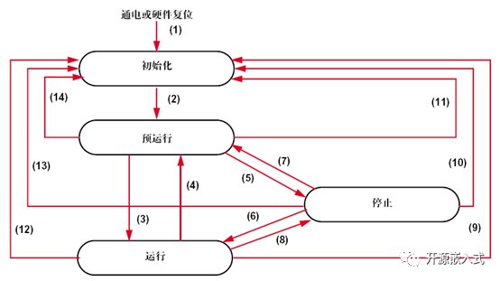
Network management state table:
-
-
Status Transition
Description
(1)
Automatically initialize after power on
(2)
Automatically enter pre-operational state after initialization
(3),(6)
Start remote node
(4),(7)
Enter pre-operational state
(5)(8)
Stop remote node
(9),(10),(11)
Reset node
(12),(13),(14)
Reset communication
Based on the state of the node, the following services are provided:
Initialization
Pre-operational
Operational
Stopped
PDO
√
SDO
√
√
Boot Start
√
√
Network Management
√
√
√
Error Control
√
√
-
Process Data Object (PDO) Services
Process Data Objects are used for transmitting process data between nodes, such as reading and setting I/O status of I/O modules, analog data collection, and analog output, etc. This protocol considers the hardware limitations of slaves, supporting a maximum of 4 groups of PDOs, each group containing one RPDO and one TPDO. Taking the I/O module as an example:
Assuming the I/O module has 24 inputs and 24 outputs, 24 inputs are transmitted to the monitoring terminal or other nodes through TPDO, and 24 outputs are set by the control node through RPDO. Using one sending and receiving PDO group, the identifiers are TPDO: 0x180 + NODE_ID, RPDO: 0x200 + NODE_ID, and 3 bytes can represent 24 I/O quantities, thus sending and receiving PDO can be represented as follows (assuming NODE_ID=1):
COB-ID
0-byte
1-byte
2-byte
385 (0x181)
Data: Input I/O status
Input_Digital_1
Input_Digital_2
Input_Digital_3
COB-ID
0-byte
1-byte
2-byte
513 (0x201)
Data: Output I/O status
Output_Digital_1
Output_Digital_2
Output_Digital_3
If it is an 8-channel analog collection module, two TPDOs are needed to transmit the collected data, without requiring RPDO, as each channel generates a 16-bit data, totaling 16 bytes, and each TPDO can only transmit 8 bytes. The two TPDO identifiers are: 0x180 + NODE_ID, 0x280 + NODE_ID.
The data frame format is as follows (assuming NODE_ID=2):
TPDO1
COB-ID
0-1 byte
2-3 byte
4-5 byte
6-7 byte
385 (0x182)
Data: Input analog
Output_Analog_1
Output_Analog_2
Output_Analog_3
Output_Analog_4
TPDO2
COB-ID
0-1 byte
2-3 byte
4-5 byte
6-7 byte
385 (0x182)
Data: Input analog
Output_Analog_5
Output_Analog_6
Output_Analog_7
Output_Analog_8
-
I/O node ← Monitoring terminal (RPDO)
-
I/O node → Monitoring terminal (TPDO)
-
Service Data Object (SDO) Services
Service Data Objects are used to read and write the object dictionary of nodes. Currently, only full-speed mode for SDO download and upload is implemented, normal mode is not supported, nor is block download and upload, because the data volume is not large, and the implemented functionalities are sufficient. Full-speed SDO download and upload use a request-response service, where the monitoring terminal sends a service request to the node, and the node returns a response.
Assuming a certain node NODE_ID=3, the protocol message is as follows:
Read node OD
Assuming, read SDO index = 0x1018 subindex = 0x00, the returned data is 1 byte data=0x04
Monitoring terminal → Node (terminal request)
COB-ID
0-byte
1-byte
2-byte
3-byte
4-byte
5-byte
6-byte
7-byte
1539 (0x603)
Command
Index
Subindex
Reserved
0x40
0x18
0x10
0x00
0x00
0x00
0x00
0x00
Monitoring terminal ← Node (node response)
COB-ID
0-byte
1-byte
2-byte
3-byte
4-byte
5-byte
6-byte
7-byte
1411 (0x583)
Command
Index
Subindex
Data
Fill up to 8 bytes
0x4F
0x18
0x10
0x00
0x04
0x00
0x00
0x00
Write node OD
Assuming, write SDO index=0x1017, subindex=0x00, write data is 0x07D0
Monitoring terminal → Node (terminal request)
COB-ID
0-byte
1-byte
2-byte
3-byte
4-byte
5-byte
6-byte
7-byte
1539 (0x603)
Command
Index
Subindex
Data to write
Fill up to 8 bytes
0x2B
0x17
0x10
0x00
0xD0
0x07
0x00
0x00
Monitoring terminal ← Node (node response)
COB-ID
0-byte
1-byte
2-byte
3-byte
4-byte
5-byte
6-byte
7-byte
1411 (0x583)
Command
Index
Subindex
Fill up to 8 bytes
0x60
0x18
0x10
0x00
0x00
0x00
0x00
0x00
If the request sent by the monitoring terminal results in an error during processing by the node, the SDO abort message will be returned, as follows:
COB-ID
0-byte
1-byte
2-byte
3-byte
4-byte
5-byte
6-byte
7-byte
1411 (0x583)
Command
Index
Subindex
Error Code
0x80
0x18
0x10
0x00
0-7 bits
8-15 bits
16-23 bits
24-31 bits
The error codes returned by the node are as follows:
SDO_ABORT_UNSUPPORTED 0x06010000UL Function not supported
SDO_ABORT_NOT_EXISTS 0x06020000UL Non-existent index
SDO_ABORT_READONLY 0x06010002UL Read-only, cannot write
SDO_ABORT_TYPEMISMATCH 0x06070010UL Type mismatch
SDO_ABORT_UNKNOWN_COMMAND 0x05040001UL Unknown command
SDO_ABORT_UNKNOWNSUB 0x06090011UL Unknown subindex
Note: Please refer to the CANOpen protocol document DS301 for the meaning of the command byte.
-
Error Control – Heartbeat Protocol
Error control is used to understand the status of each node on the bus. This article only implements the heartbeat protocol, where each node periodically sends heartbeat messages to the monitoring terminal to report its status. The message is as follows:
Assuming NODE_ID=2
Node → Monitoring terminal
COB-ID
0-byte
1794 (0x702)
Node status
0x00
The returned status is as follows:
Status Code
Status Meaning
0x00
BOOTUP Startup Status
0x04
STOPPED Stopped
0x05
OPERATIONAL Operational
0x7F
PRE-OPERATIONAL Pre-operational
After startup, the node sends a BOOTUP heartbeat, and then sends heartbeat message frames at a fixed frequency. The monitoring terminal receives this message to detect the node’s status.
Our official QQ group 1: 281549832
Special thanks to the strong support from netizens.
Our open-source team is constantly expanding, and we hope everyone will join us!
Here, we would like to thank everyone for their strong support!

Everyone, please pay attention!