5, CANopen Protocol Stack Communication Unit Implementation
The communication unit in the CANopen protocol first classifies NMT, SDO, PDO, and synchronization messages based on the identifier. Then, different types of messages are processed by independent sub-modules. After the system is powered on and initialized, it enters the pre-operational state and sends a heartbeat message to the bus indicating that the node is ready. At this time, the node can only process NMT messages. After waiting for the NMT message to enter the operational state, the node begins to accept SDO messages, PDO messages, and synchronization message requests. The message processing flow of the driver is shown in the figure.
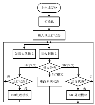
The network management function mainly includes sending heartbeat messages, processing NMT messages to switch the node state machine, and sending emergency messages. After the node enters the pre-operational state, it starts sending heartbeat messages to broadcast its status to other devices on the bus. The identifier for the heartbeat message is 0x700+NodeID, and a one-byte status word indicates the current state of the node, as defined in the table.
The node state machine defines three states: pre-operational, operational, and stopped. The NMT message not only allows the node to switch between these three states but also sends node initialization commands to reset the node and sends communication initialization commands
to reinitialize the protocol stack.

The NMT message identifier is 0000H, composed of 2 bytes of data. The first byte is the operation code, which stores the command character, as defined in the table.
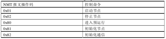
After the node receives the NMT message, it first checks whether the node ID matches its own. If they match, it continues to parse the operation code and switch to the corresponding state. If the operation code is unrecognized, it returns 0. The NMT message processing flow is shown in the figure.
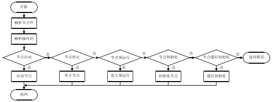
SDO Message Processing Flow
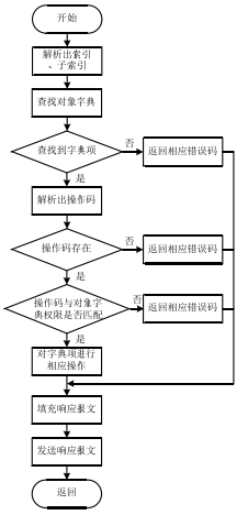
SDO messages are mainly used to access the object dictionary for reading and writing, implementing tasks such as setting node parameters that do not have high real-time requirements. SDO message frame data consists of 8 bytes, where the first byte is the function code indicating read or write operations, followed by three bytes for the object dictionary index and sub-index. After receiving an SDO message, the sub-node first parses the index and sub-index, finds the corresponding entry according to the lookup method in the previous section’s object dictionary, and then parses the operation code. If it matches the read/write permissions of the object dictionary, the processing program is completed. After processing, the sub-node sends a response message. If successful, the data sent includes the success operation code, index, sub-index, and object dictionary data; otherwise, it sends a failure operation code, index, and sub-index.
The SDO message processing flow is shown in the figure.
PDO Message Processing Flow
PDO messages are the most numerous and important communication objects in CAN communication. PDO messages are divided into sending PDO and receiving PDO types. Receiving master station control commands, interpolating step signals, and synchronizing multiple axes in multi-axis motion control systems all rely on rapid and efficient PDO messages.
As mentioned earlier, to improve the efficiency of receiving and sending PDO messages and enhance the real-time performance of PDO communication, object dictionary mapping technology is used. To reduce system overhead, the sending PDO message prohibition time and event cycle are defined. To improve the synchronization of PDO communication, synchronous PDO and asynchronous PDO transmissions are implemented.
(1) Object Dictionary Mapping
PDO directly mapping the object dictionary has two major advantages: first, it eliminates the complex lookup process of the object dictionary, allowing direct read and write to the mapped object, reducing the processing time of PDO messages and improving communication real-time performance; second, due to direct mapping, there is no need for operation codes, indexes, and sub-indexes, allowing the 8-byte data field to store all data, resulting in each message frame transmitting twice as much data as SDO messages, thus improving transmission efficiency. The mapping method of the object dictionary includes fixed mapping and dynamic mapping; the latter can be modified in the object dictionary. However, considering user convenience, preventing misconfiguration, and reducing development difficulty, a predefined fixed mapping mode is adopted.
(2) PDO Message Sending Control
Since it is not feasible to continuously send PDO messages, as this would waste node system resources, and numerous nodes continuously sending PDO messages would cause bus network congestion, the CANopen protocol defines the sending PDO event cycle. If the system state variable has not changed, a PDO message is sent every event cycle; if the system state variable changes suddenly, data is sent immediately. The sending PDO event cycle is optional; if not set, it defaults to sending a PDO message only when the variable changes. When multiple nodes on the bus send PDO messages simultaneously, if a node detects a bus conflict and exits, if multiple nodes immediately resend, it will continuously cause bus conflicts. Therefore, after a PDO message sending fails, it must wait for a prohibition event before resending. The sending PDO control parameter structure is defined as follows:
typedef struct
{
CanTxMsg CAN; //Message to be sent
u16 event_time; //Event cycle
u16 event_timestamp; // Event cycle timestamp
u16 inhibit_time; // Prohibition time
u16 inhibit_timestamp; //Prohibition time timestamp
u8 inhibit_status; // Prohibition sending status
…………… //Omitted below
} TPDO_CONFIG;
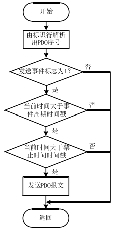
TPDO_CONFIG also introduces the concept of timestamps, which record the next sending time of the PDO message, which is the current time plus the event cycle or prohibition time. The timestamp is updated after each successful or failed PDO message sending. The sending PDO message sending flow is shown in the figure.
Synchronous PDO and Asynchronous PDO
The triggering method for PDO messages is represented by a one-byte transmission type value. The CANopen regulations on PDO message transmission types are shown in the table.
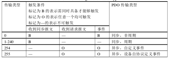
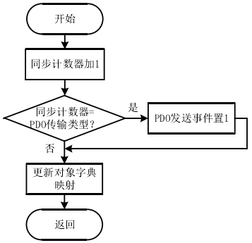
We generally use PDO transmission types from 1-240, where the number indicates after how many synchronization messages to send the PDO message. That is, after receiving a synchronization message, the synchronization counter is incremented by 1, and then compared with the transmission type. If it is greater than or equal, the PDO message is sent immediately. The synchronization message processing flow is shown in the figure.
Implementation of CANopen Protocol Stack Application Program Unit
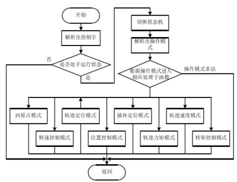
The application program unit completes the three closed-loop motor control algorithms based on parameters and control commands in the object dictionary. This part of the program flow has been detailed in Chapter Four. For the CANopen protocol-based servo drive, our main task is to integrate the CANopen drive with the motion control sub-protocol DS-402 into the existing control algorithm, enabling the drive to “understand” the control commands from the communication unit and to fill the drive’s state variables into the object dictionary in the specified format. When the servo drive is operating normally, the drive and the master node need to continuously transmit control commands and state variables. The DS-402 device protocol defines six operating modes, while the original drive defines three control modes, requiring reasonable allocation of PDO mapping. The table maps the parameters, control commands, and state monitoring required for the drive’s various operating modes to the corresponding entries in the object dictionary to PDO messages.
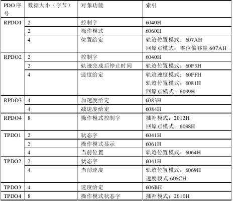
After the drive receives the PDO message, it checks the node state machine. If it is in the operational state, it immediately parses the control commands and parameter settings, entering the corresponding operation mode sub-module. The program flow is shown in the figure.
Original text reprinted from: “Research on AC Servo Drive Based on CANopen Protocol”
Author: Huang JianSchool of Electronic Information and Electrical Engineering, Shanghai Jiao Tong University