
Welcome to Xiao Ni Technical Classroom
Here, we can provide you with
• A wealth of knowledge on servo drive series products
• Detailed technical practical guidance
• Comprehensive troubleshooting analysis
At the same time, our technical experts provide a professional Q&A platform 400-887-9230, and you are welcome to leave us a message anytime!
System Configuration
Hardware: WAGO PLC750-8206
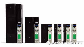
Driver: M701-03200050A
Firmware: 01.15.00.00
Communication Card: SI-EtherCAT
Firmware: 01.04.00.12
Software:
CoDeSys PLC_Pro
SI-CANopen EDS Files
Operating Steps
1. Import EDS Files
Add the required EDS files to the dedicated EDS folder of the PLC software.
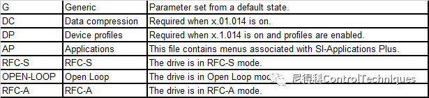
Explanation of the EDS file suffix is as follows:
<< Click to view the full image >>
2. Add Drivers
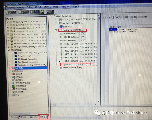
In the resource page – ‘PLC Configuration Item’ – right-click on the ‘CANopen-Master’ node to add a sub-device, right-click – ‘Properties’ to select the device mode, you can choose synchronous or asynchronous. In this example, the real-time control requirement for the driver is low, to avoid occupying bus resources, select asynchronous mode.
3. PDO Configuration
SI-CANopen PDO configuration can be done using the upper computer configuration or the inverter parameter configuration, but the upper computer configuration has a higher priority. Note that the information configured in the upper computer will not be synchronized to the driver parameters. In this example, the upper computer configuration is used, where the upper computer sends configuration information to each node in SDO mode during device initialization. You can also choose to configure each node once during the debugging phase and save it. After that, the configuration information will not be sent during each power-on initialization.
PDO is divided into TPDO (node to upper computer) and RPDO (upper computer to node) based on the transmission direction. SI-CANopen supports 4 PDOs, namely PDOA-D, with PDO numbers PDO1, PDO3, PDO5, PDO6. The specific PDO configuration process is as follows:
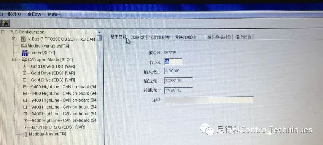
3.1 Basic Parameter Configuration Input device node ID, in this example, it is 25 (0x19).
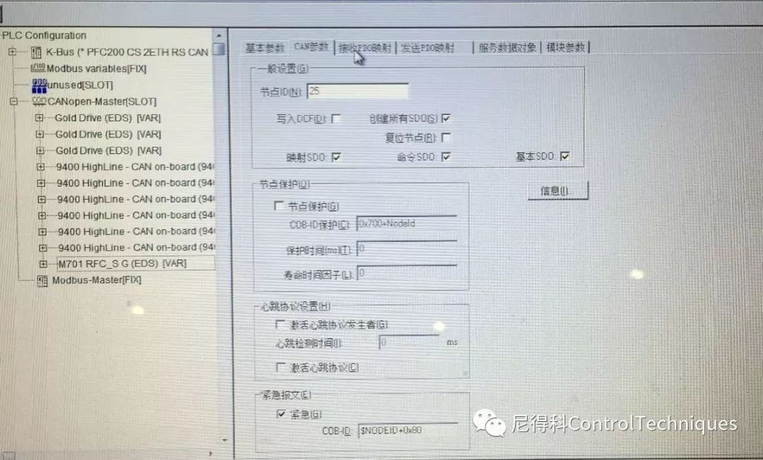
3.2 CAN Parameter Settings
This page selects the type of SDO for the configuration phase, and here you need to check to create all SDOs.
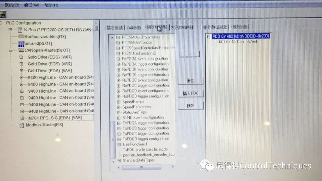
3.3 Receiving PDO (TxPDO) Settings
By default, PDOA(0), PDOB(3), PDOC(5), PDOD(6) are already added, and only PDO0 has mapping parameter settings. According to needs, add mapping parameters under each PDO. Unnecessary mappings can be deleted to reduce the amount of data during the configuration process, which can significantly reduce the initialization configuration process when there are many network nodes.
It should be noted that each PDO has 64 data bits, and by default, it is configured with 2 32-bit parameters. If the actual bits of this parameter are less than 32 bits, SI-CANopen will extend this parameter to 32 bits. You can also set x.01.014 to configure the PDO mapping to 16 bits, in which case a specific EDS file is required. However, if the actual bits of the parameter are 32 bits, this mapping will still occupy 32 bits in the PDO.
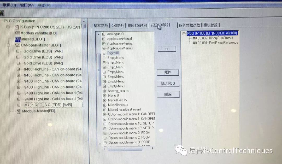
3.4 Sending PDO Mapping
Select the parameters that the PLC needs to read and configure them to the output PDO (TxPDO).
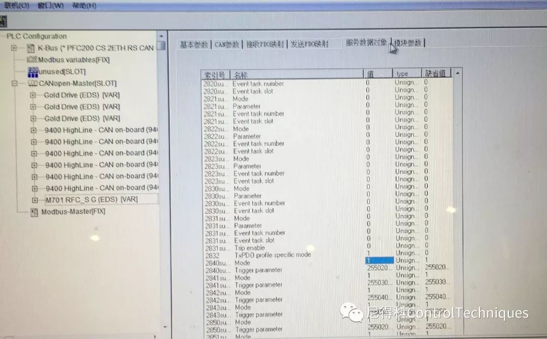
3.5 Service Data Object (SDO) Configuration
In asynchronous mode, the TxPDO transmission mode is set to upload when the mapping parameters change. Set the 0x2832 sub-index 00 to 1.
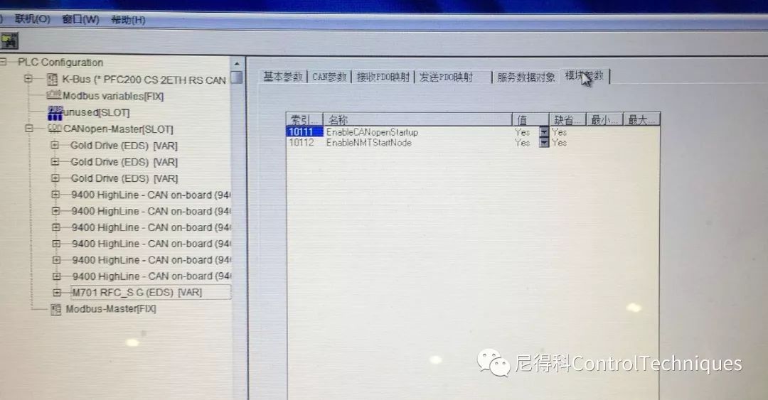
3.6 Module Parameter Settings
10111 enables the upper computer configuration function. If NO is selected, the PDO configuration will use the driver parameters.
4. Driver Parameter Settings
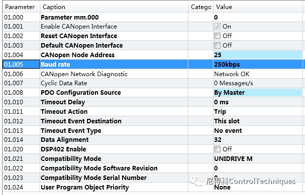
The driver’s parameters only need to set the X.01.004 node address to be consistent with the upper computer configuration, and the baud rate X.01.005 is set to the upper computer baud rate or auto-detect. After setting, set X.01.002 to ON to reset CANopen, and save the driver parameters. X.01.008 defaults to By menu, which uses the driver parameters to configure the PDO mapping. However, if the upper computer configuration is used, this parameter will automatically change to By Master.
After the settings are completed, the PLC will automatically assign the corresponding input and output register addresses to each PDO, and users can read and write to the corresponding registers in the program. It should be noted that the upper computer PDO mapping configuration will not be updated to the driver parameter menu X.02-X.05 group.
PDO Transmission Mode
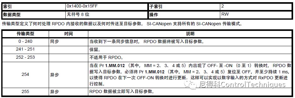
RxPDO Transmission Mode
As shown in the table below, in synchronous mode, data is written to the target parameter at the next synchronization information, while in asynchronous mode, the default value is 255, meaning data is immediately written to the target parameter.
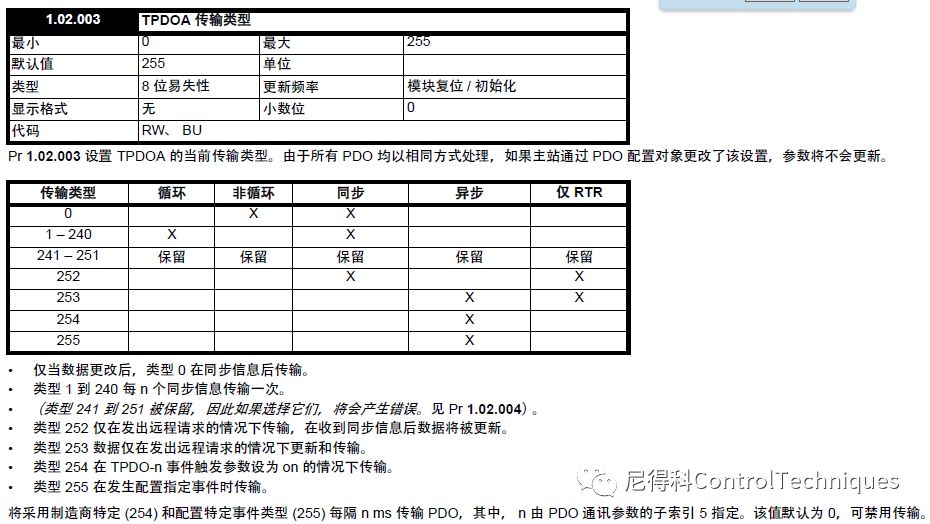
TPDO Transmission Mode
In the figure below, X represents various modes supported by TPDO in different transmission modes. In this example, it is asynchronous mode, with the default transmission mode set to 255 (time-triggered). To reduce the amount of sending, the trigger time is set to 0 (default value), disabling time-triggered. By configuring the specific mode OD(0X2832)=1, the TPDO is set to send when the data changes.


Appendix: CANopen Messages
During debugging and handling CANopen communication, you can use a USB-CAN analyzer in parallel on the bus to monitor and analyze the entire configuration and communication process through PC software.
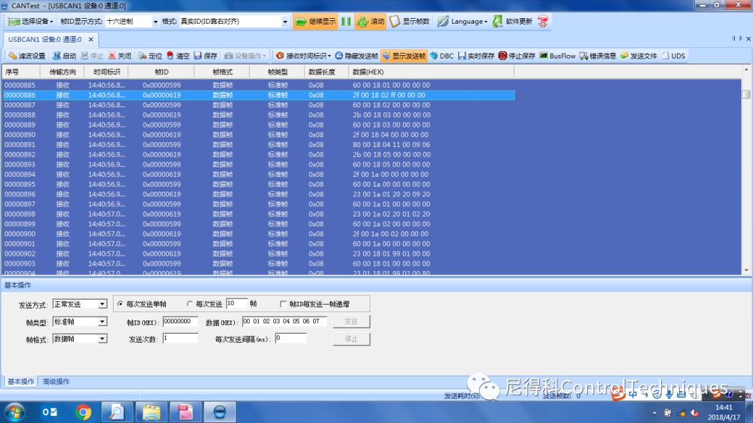
The table below shows the upper computer configured with nodes 01, 02, and 25 (0x19, M700 driver), but the configuration and communication process when nodes 01 and 02 are not connected. The configuration process can be found in the “SI-CANopen User Guide issue2”.
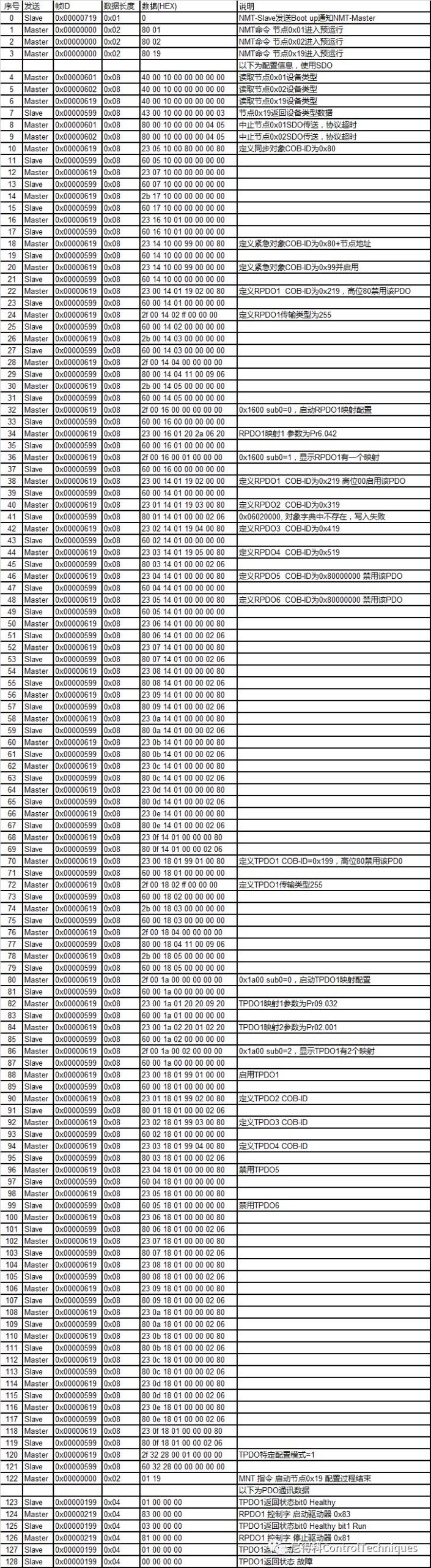
<< Click to view the full image >>

For more information on M700, please click below“Read the original text”

Nidec Control Techniques
WeChat ID: NidecCT
Email: [email protected]
Follow us for more servo solution unlocks