
One-Button Control of Motor Start/Stop via PLC
1. Project Description
In industrial production processes, it is common to use a button to control the start and stop of motors. This is often used in quick travel and ground operation scenarios. A typical application is as follows: when the motor is required to operate, pressing button SB energizes the coil of the AC contactor KM, allowing three-phase AC power to connect to the motor through the contactor’s main contacts, thus starting the motor; when the button SB is released, the contactor coil loses power, the magnetic force disappears, the contactor releases, and the motor stops running.
2. Preparation List
See Table 5-1.
Table 5-1 Preparation List
|
Item No. |
Equipment |
Parameters |
Quantity |
Remarks |
|
1 |
Computer |
Installed with SiemensTIA Portal V14 |
1 |
|
|
2 |
PLC |
S6-1214C DC/DC/DC |
1 |
With network cable |
|
3 |
Signal Module |
SM 1223/DI8×24V DC,DQ8×RLY |
1 |
|
|
4 |
DC Power Supply |
AC220V/DC24V/5A |
1 |
|
|
5 |
Button |
1 Normally Open |
1 |
|
|
6 |
Contactor |
Coil DC 24V |
1 |
|
|
7 |
Mini Circuit Breaker |
10A |
1 |
|
|
8 |
Thermal Relay |
1 |
||
|
9 |
Three-Phase Asynchronous Motor |
1 |
||
|
10 |
Rail |
35mm |
1 |
|
|
11 |
Wires |
0.75mm2 |
20 |
3. Control Requirements
Currently, there is an AC three-phase asynchronous motor with only one self-resetting normally open button SB0. According to engineering requirements, the motor should rotate forward for 20s, stop for 5s, and then rotate forward for another 20s, stopping for 5s, and continue this cycle. Pressing SB0 starts the motor, pressing SB0 again pauses the motor (time does not reset), pressing SB0 again resumes the motor, and so on.
Long pressing button SB0 for 5s stops the motor and resets the system.
The system is equipped with necessary overload and overcurrent protection.
4. Electrical Circuit Diagram
Figure 5-1 shows the main circuit of the motor; Figure 5-2 shows the input signal terminal diagram, which includes 2 input signals: one “Start/Stop” button and one motor thermal overload protection input signal KH; Figure 5-3 shows the output signal terminal diagram, which has only one output signal for the coil of contactor KM.
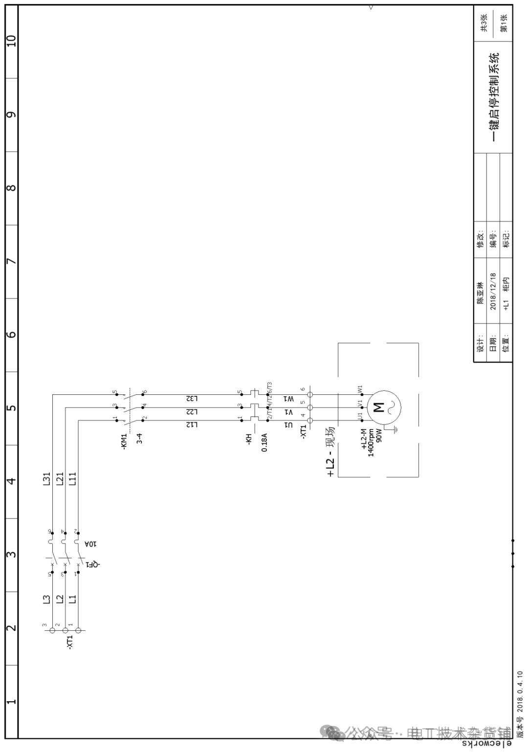
Figure5–1 Main Electrical Circuit Diagram
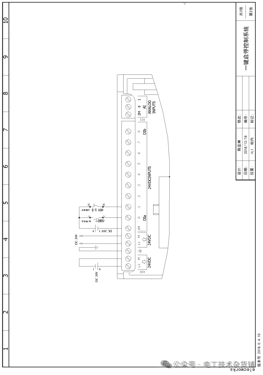
Figure5–2 PLC Input Circuit Diagram
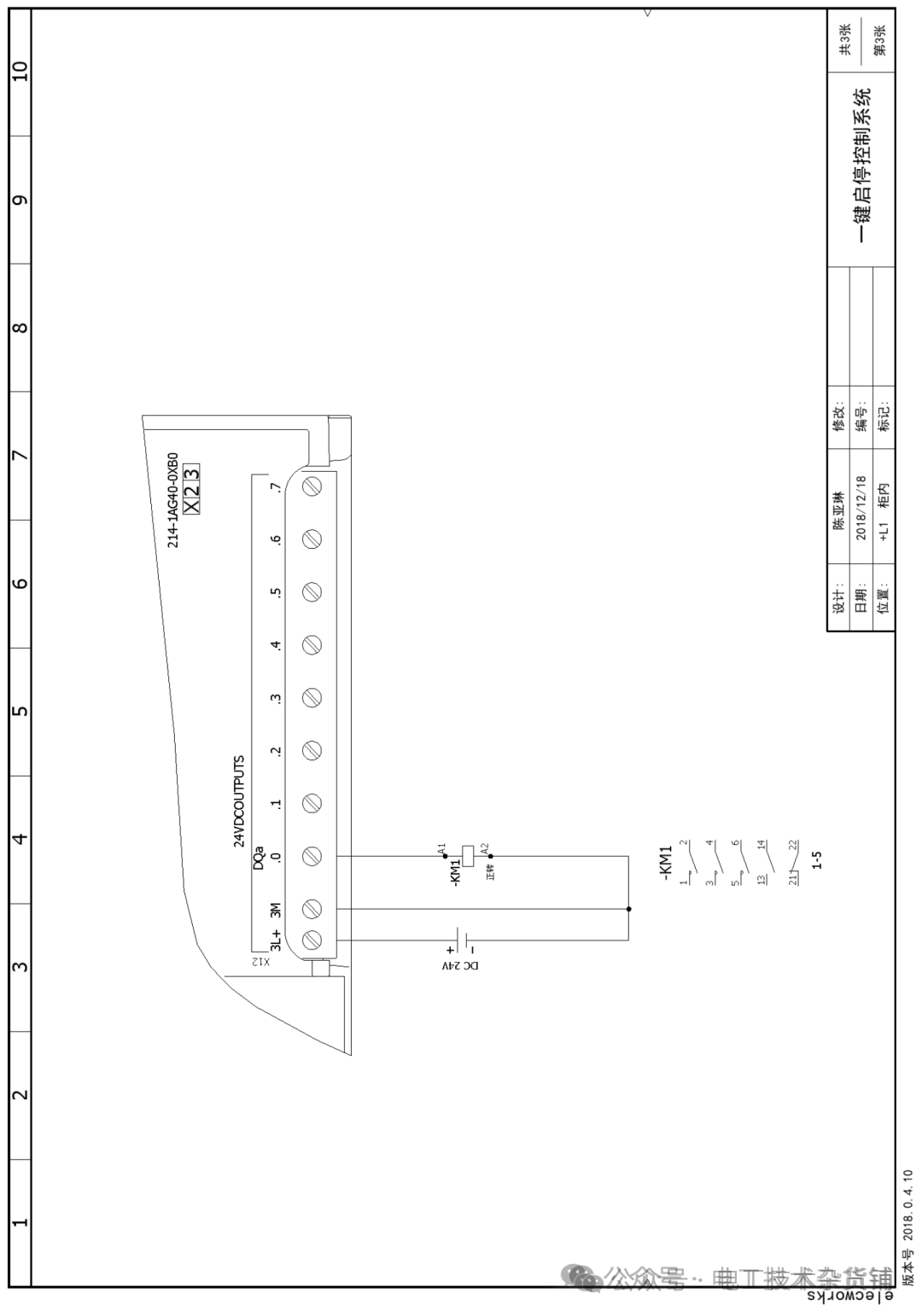
Figure5–3 PLC Output Circuit Diagram
5. PLC Reference Program
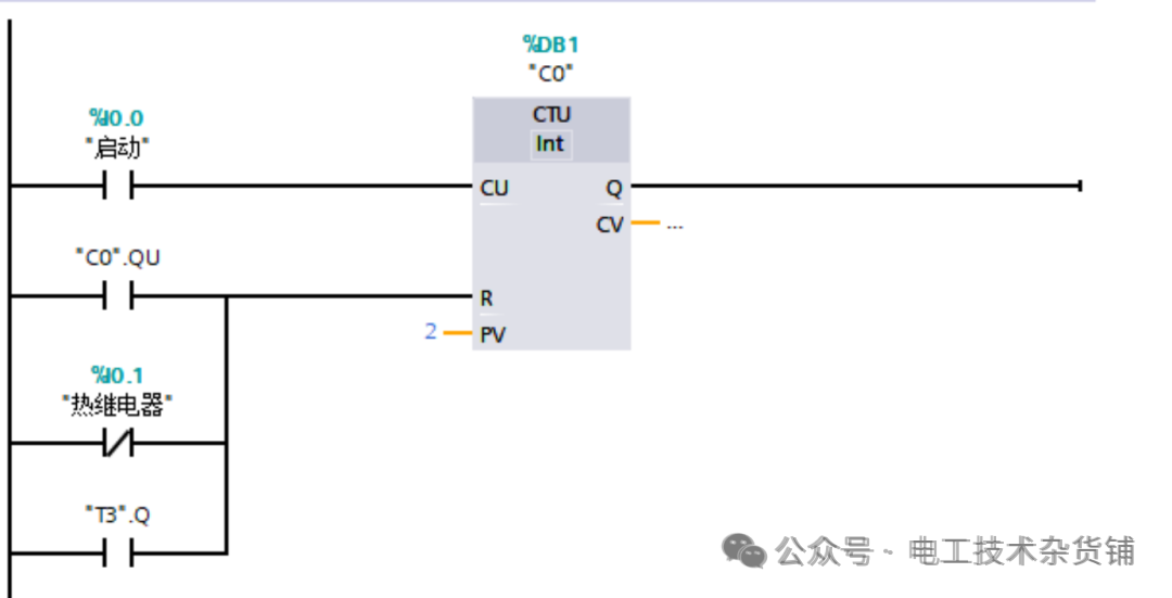
Figure 5-4 PLC Reference Program 1
In Figure 5-4, when the start/stop button SB is pressed (sending a start signal), the contact I0.0 closes, and the current value of counter C0 in the PLC program increases by 1 (from 0 to 1); in the program of Figure 5-4, if button SB is pressed again when the current value of C0 is 1 (sending a stop signal), the current value of C0 changes from 1 to 2, at which point the current value of C0 equals the set value, the normally open contact of C0 closes, the current value of the counter is reset to 0, and the normally open contact of C0 opens again.
When the thermal overload protection input signal KH of the motor is activated, the normally open contact I0.1 closes, the current value of the counter is reset to 0, and the normally open contact of C0 opens.
It is important to note that when the normally open contact of T3 closes (T3 closes when the button SB is pressed for 5 seconds), the current value of the counter is reset to 0, and the normally open contact of C0 opens.
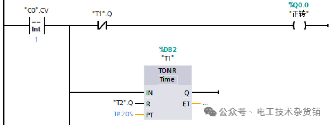
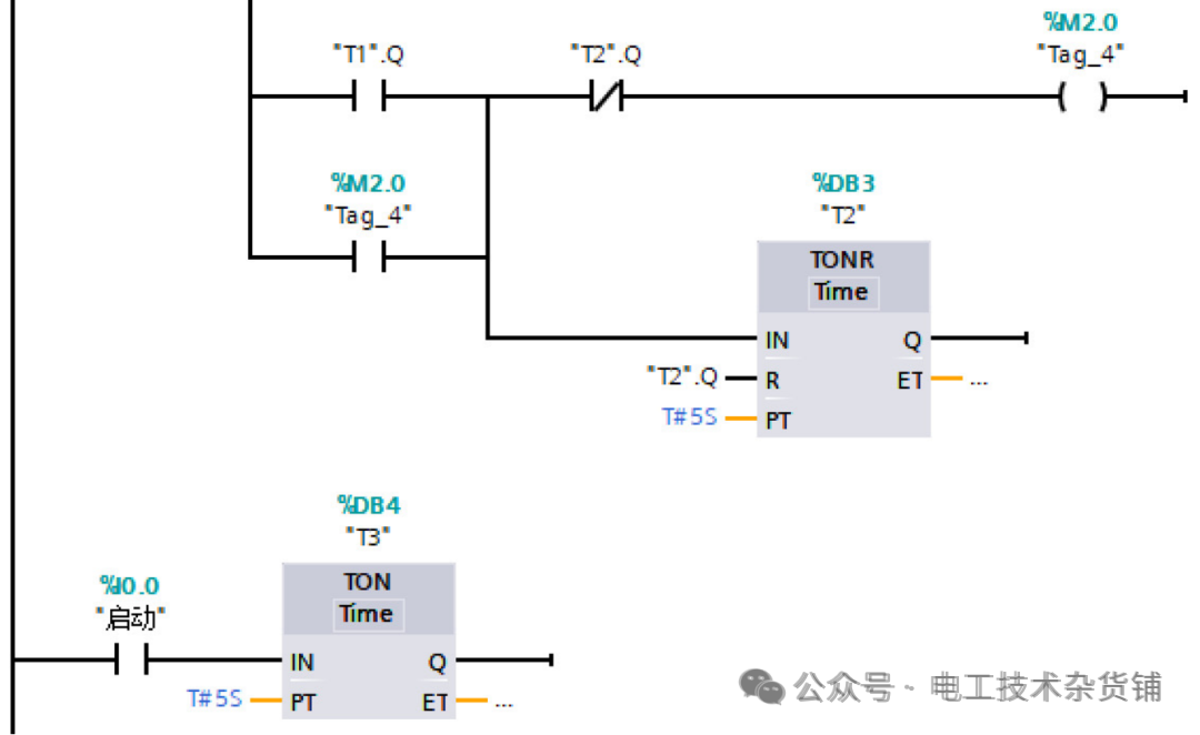
Figure 5-5 PLC Reference Program 2
After sending the start signal, the current value of C0 is “1”, and the comparison instruction contact in the PLC program closes, at which point the coil Q0.0 is energized, the contactor KM is energized, and the motor runs; at this time, the on-delay timer T1 starts timing, and after the delay time (set to 20 seconds), the normally closed contact of T1 opens, the coil Q0.0 loses power, the coil of contactor KM loses power, and the motor stops running; when the delay time of T1 is reached, the normally open contact of T1 closes, the auxiliary relay M2.0 is energized for self-locking, and the on-delay timer T2 coil is energized to start timing; after the delay time (set to 5 seconds), the current values of timers T1 and T2 are reset, the normally closed contacts of T1 and T2 return to closed, the coil Q0.0 is re-energized, the contactor KM is energized again, and the motor runs again.
After sending the stop signal, the current value of C0 changes from 1 to “2” and then resets to “0” in the next scan cycle; in the PLC program, the comparison contact opens, and the coils of T1 and T2 lose power, but since T1 and T2 are on-delay timers, their current values will not be reset to “0” when the timer coils lose power; when a start signal is sent again, the system can continue to run according to the state before the power loss.
When button SB is pressed, and contact I0.0 closes, timer T3 starts timing; when the delay time is reached (set to 5 seconds), the normally open contact of T3 closes, the system stops, and the current values of T1 and T2 are reset to “0”.
When the thermal overload protection is activated, signal I0.0 is present, the system stops, and the current values of T1 and T2 are reset to “0”.
Copyright Notice: This article is reprinted from the internet, and the copyright belongs to the original author. It is not for any other commercial use. If there are any copyright issues, please notify us to delete it promptly. Thank you!

Long press—select “Identify the QR code in the image” to follow