Configuring I-Device in the same project
I-Device refers to IO devices equipped with a CPU. All CPUs of the S7-1500 PLC and S7-1200 PLC can function as I-Devices and IO controllers.
Below is an example demonstration of motor control using the I-Device functionality.
The CPU1511-1 PN of the S7-1500 PLC communicates with the CPU1214C AC/DC/RLY of the S7-1200 PLC via PROFINET, as shown in the figure. In the figure, the CPU1214C acts as an I-Device smart device communicating with the CPU1511-1 PN.
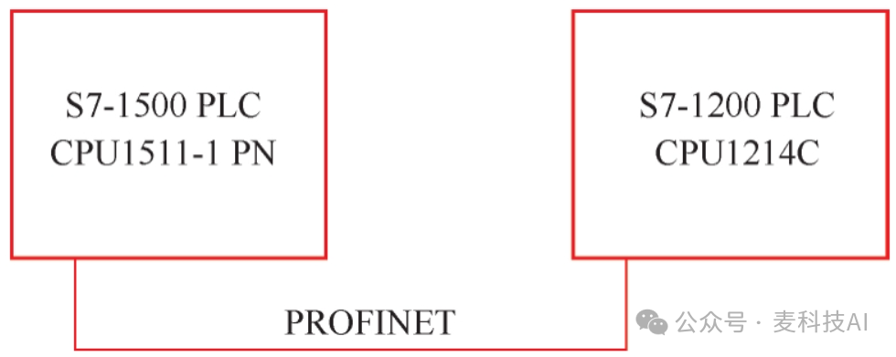
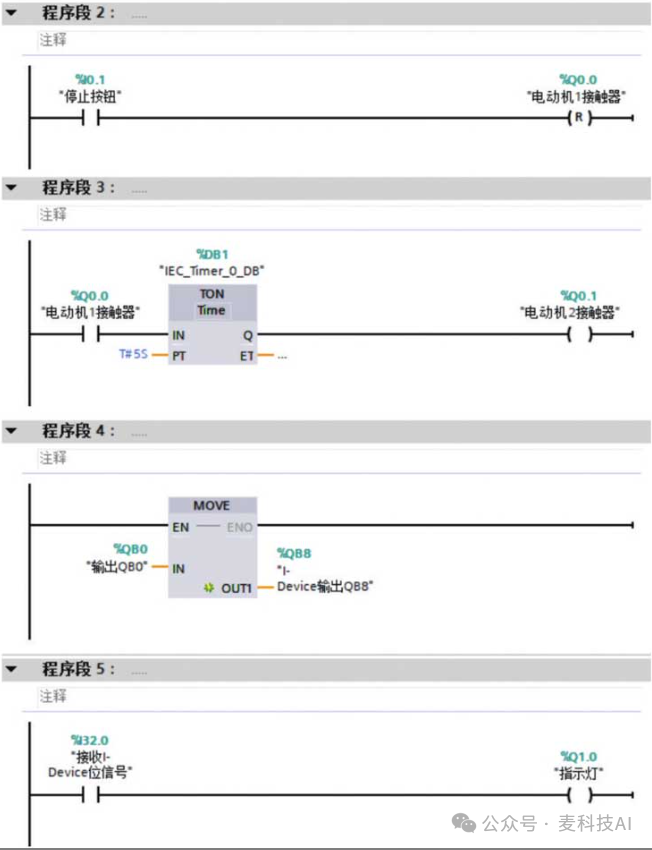
(1) S7-1500 PLC: There are two motors and two buttons, where SB1 is the start button and SB2 is the stop button, both wired as normally open contacts. When the start button is pressed, motor 1 starts immediately, and motor 2 starts after a 5-second delay. When the stop button is pressed, both motors stop. The status bytes of both motors are transmitted to the S7-1200 PLC, while the output reflects the status value of the selector switch sent from the S7-1200 PLC.
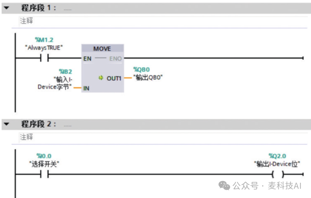
(2) S7-1200 PLC: Displays a byte transmitted from the S7-1500 PLC on Q0.0 to Q0.7, and sends the status value of the selector switch I0.0 to the S7-1500 PLC for display.
Steps and Analysis
(1) Create a new project, insert CPU1511-1 PN as the IO controller, and CPU1214C as the I-Device smart device, as shown in the figure.
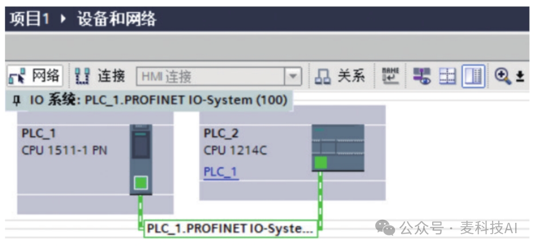
Ensure that the Ethernet interfaces of both CPUs are on the same subnet. Click on the properties of PLC_2, enable “IO Device” in the “Operating Mode” option, and assign it to the IO controller. In the “Transfer Area” option, you can change the address and the direction of the transfer area.
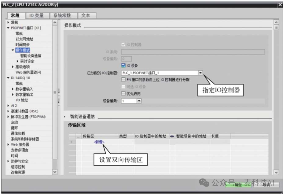
After specifying the IO controller, the “Smart Device Communication” section appears in the “Operating Mode” option. Click to configure the communication transfer area, double-click “Add New” to create a transfer area, and define the communication address areas for both parties: use the Q area as the data sending area; use the I area as the data receiving area. Clicking the arrow can change the direction of data transfer. The figure shows the two created transfer areas, both with a communication length of 1 byte.
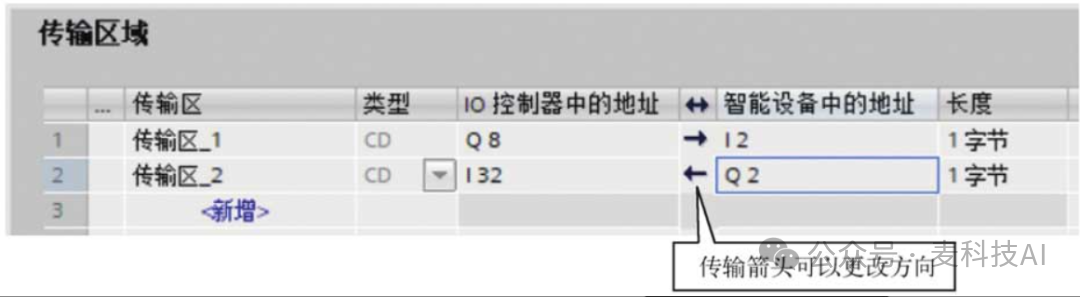
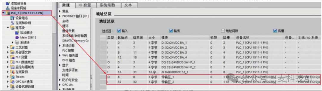
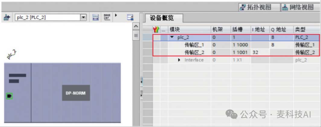
(2) The figure shows the address overview of the IO controller. Download the configuration data to both CPUs, and the PROFINET IO communication between them will be automatically established. The IO controller (CPU1511-1 PN) uses QB8 to send data to the I-Device (CPU1214C) IB2; the I-Device uses QB2 to send data to the IO controller’s IB32. In this example, the CPU1214C serves as both an IO device for the upper-level IO controller and as an IO controller for the lower-level IO device, providing great flexibility and convenience.
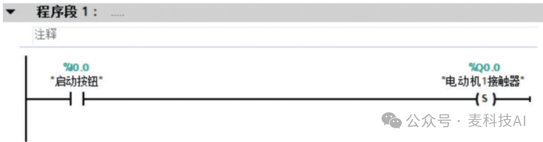
(3) Program both PLCs separately; no programming is required for the communication part, which is also an advantage of the I-Device. The figure shows the main program of CPU1511-1 PN. Program segment 1 and segment 2 are for starting and stopping motor 1. Program segment 3 activates a delay timer TON after motor 1 is turned on for 5 seconds. Program segment 4 outputs the QB0 byte value to the I-Device. Program segment 5 receives bit signals from the I-Device.
The figure shows the main program of CPU1214C. Program segment 1 receives the byte signal from the IO controller and outputs it to QB0. Program segment 2 sends the status of the selector switch I0.0 to Q2.0 of the IO controller.
Configuring I-Device in different projects
Implementing motor control through I-Device functionality (PLC files not in the same project)Example
Based on the above example, an additional requirement is added, namely that the files of the two PLCs must be configured in different projects.
Steps and Analysis
(1) Create a new project, insert CPU1214C as the I-Device, click on the Ethernet interface, enable “IO Device” in the properties interface under the “Operating Mode” option, select “Unassigned” in the “Assigned IO Controller” option, and define the communication address areas for both parties in the transfer area, as shown in the figure.
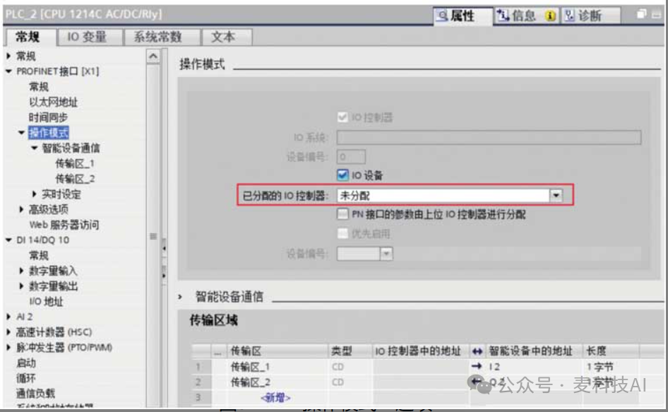
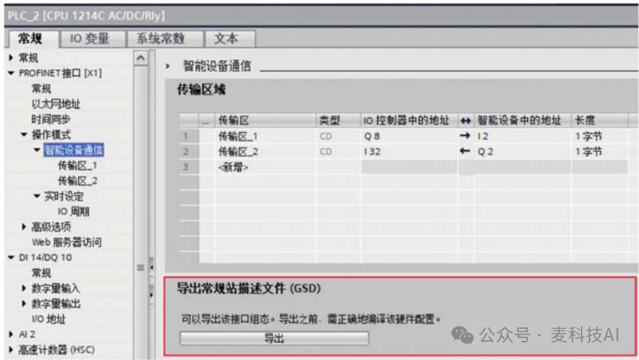
Similar to the previous example, after creating two transfer areas, you can view the “Export General Station Description File (GSD)” section at the end of the “Smart Device Communication” option, as shown in the figure. Click the “Export” button to generate a GSD file, which contains configuration information for IO communication, as shown in the figure.
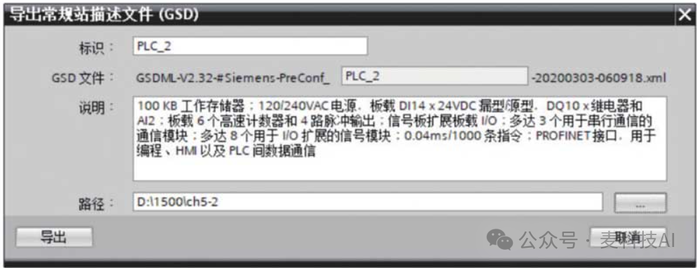
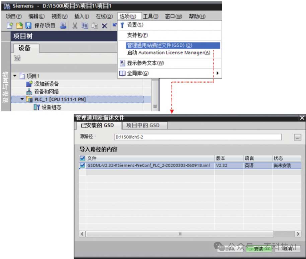
Copy the “GSDML-V2.32-#Siemens-PreConf_PLC_2-20200303-060918.xml” GSD file to the computer configuring the IO controller and import it into the project.
(2) Additionally, create a new project for the IO controller, inserting CPU1511-1 PN, setting the IP address of the Ethernet interface to be in the same subnet as the IO device, importing the GSD file, and installing the relevant content of the GSD file, as shown in the figure.
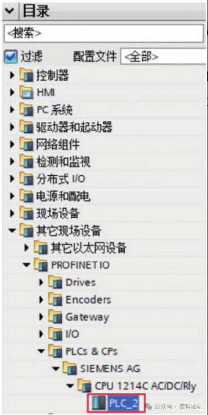
Open the hardware catalog as shown in the figure, select “Other Field Devices” → “PROFINET IO”, and drag the installed I-Device site PLC_2 into the network view, as shown in the figure. This site is the GSD device_1, not the actual PLC name.
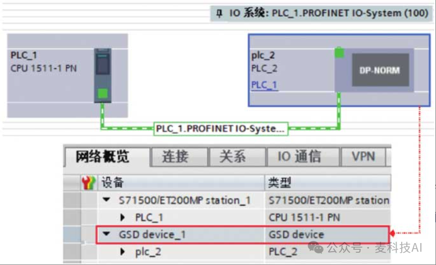
Once the IO controller is connected to the IO device’s port, the data transfer area of the I-Device can be seen in the device view, as shown in the figure. Since the device name of the I-Device cannot be automatically assigned, the configured IO device name must match the device name defined when creating the project in (1).
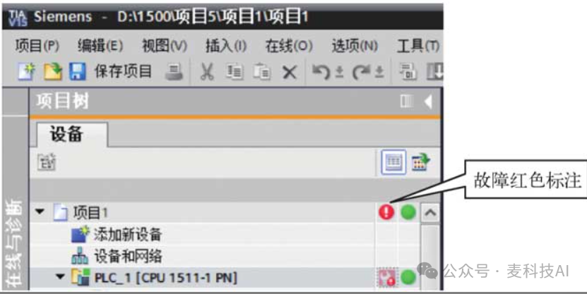
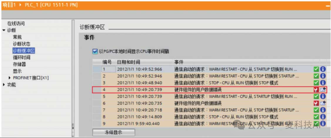
(3) Debugging. Download the configuration data to the corresponding CPUs, and the PROFINET IO communication between them will be automatically established. If any device encounters an issue, a fault will be highlighted in red, as shown in the figure, and a “User Data Error of Hardware Component” will appear in the “Diagnostic Buffer,” as shown in the figure.
That’s it, it’s done!