We are a community that helps hardware engineers with component selection references. If you are interested, please follow our public account below, where we regularly share information on new chips, chip replacements, and teardown analyses!
In-Depth Analysis of the 18V Camera PMIC SC6201Q: 3 Buck + 1 LDO
1. Descriptions
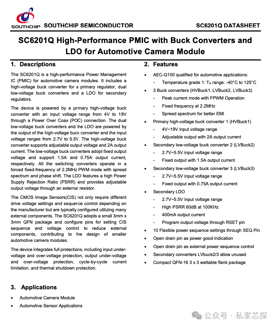
Original TextThe SC6201Q is a high-performance Power Management IC (PMIC) for automotive camera modules. It includes a high-voltage buck converter for a primary regulator, dual low-voltage buck converters and a LDO for secondary regulators.
InterpretationThe SC6201Q is a high-performance power management chip optimized for automotive camera modules, integrating:
- • 1 high-voltage Buck (main power)
- • 2 low-voltage Buck (secondary power)
- • 1 LDO (secondary power) that can provide multiple power supply solutions within a single chip, reducing external components.
Original TextThe device is powered by a primary high-voltage buck converter with an input voltage range from 4V to 19V through a Power Over Coax (POC) connection.
InterpretationThe high-voltage Buck has a wide input range (4~19V), supports POC (Power Over Coax), and is directly compatible with vehicle power system fluctuations, making it suitable for long-distance camera power supply.
Original TextThe dual low-voltage buck converters and the LDO are powered by the output of the high-voltage buck converter and the input voltage ranges from 2.7V to 5.5V.
InterpretationBoth low-voltage Buck converters and the LDO are powered by the output of the high-voltage Buck, operating in the range of 2.7~5.5V, forming a hierarchical power supply that facilitates efficiency optimization and noise isolation.
Original TextThe high-voltage buck converter supports adjustable output voltage and 2A output current. The low-voltage buck converters adopt fixed output voltage and support 1.5A and 0.75A output current, respectively.
Interpretation
- • High-voltage Buck: adjustable output voltage (2.7~5.3V), 2A current capability, compatible with various module architectures
- • Low-voltage Buck: fixed voltage (typically 1.1V, 1.8V), capable of outputting 1.5A and 0.75A, meeting the power supply needs of CIS cores and peripheral chips
Original TextAll the switching converters operate in a forced fixed-frequency of 2.2MHz PWM mode with spread spectrum and phase shift.
InterpretationAll Buck converters operate in a forced PWM mode at a fixed frequency of 2.2MHz, with spread spectrum and phase shift:
- • Avoiding AM radio interference
- • Reducing switching noise peaks, improving EMC performance
Original TextThe LDO features a high Power Supply Rejection Ratio (PSRR) and provides adjustable output voltage through an external resistor.
InterpretationThe LDO has a high power supply rejection ratio (60dB@100kHz), suitable for powering analog/RF sections; the output voltage can be adjusted through an external resistor (1.8~3.5V), flexibly adapting to different CIS or analog circuits.
Original TextThe CMOS Image Sensors(CIS) not only require different drive voltage settings and sequence control depending on the manufacturer but are typically configured utilizing many external components. The SC6201Q adopts a small 3mm x 3mm QFN package and configure pins for setting CIS sequence and voltage control to reduce external components, contributing to the design of smaller automotive camera modules.
InterpretationDifferent manufacturers’ CIS have varying requirements for supply voltage and power-up sequencing, and traditional solutions require MCU control and multiple discrete power modules. The SC6201Q allows voltage and sequencing settings directly through pins, significantly reducing external components, and with its 3×3mm QFN package, it enables smaller and easier PCB layout for modules.
Original TextThe device integrates full protections, including input under-voltage and over-voltage protection, output under-voltage and over-voltage protection, cycle-by-cycle current limitation, and thermal shutdown protection.
InterpretationIt has a complete protection mechanism built-in:
- • Input under-voltage/over-voltage (UVLO/OVP)
- • Output under-voltage/over-voltage (UVP/OVP)
- • Cycle-by-cycle current limiting (to prevent overcurrent damage)
- • Thermal shutdown (TSD) to ensure safe operation of the chip under various harsh automotive conditions.
2. Features
Here is the key specifications list that directly determines engineers’ component selection.
- • AEC-Q100 Grade 1: Full temperature range (-40°C ~ 125°C) automotive certification
- • Three Buck converters (1 high-voltage + 2 low-voltage): peak current mode, 2.2MHz fixed frequency with spread spectrum
- • High-voltage Buck (HVBuck1): 4~19V input, adjustable output, 2A current
- • Low-voltage Buck (LVBuck2/3): 2.7~5.5V input, fixed output, 1.5A/0.75A current
- • LDO: 2.7~5.5V input, high PSRR (60dB@100kHz), 400mA current, adjustable output
- • 10 selectable sequences (SEQ pins): No MCU required, adapts to different CIS power-up requirements
- • PG/EXT pins: Can be used for power good signal or external sequence control
- • LVBuck2/3 can be unused: Unused pins are automatically skipped, simplifying design
- • Package: QFN-16 3×3mm wettable flank, convenient for AOI detection
3. Applications
- • Automotive camera modules (surround view, front view, electronic rearview mirror, reversing image)
- • Automotive sensor applications (millimeter-wave radar, LiDAR, infrared sensors, etc.)
If you have any needs, please specify your company’s project requirements to:[email protected][1]
Teardown Report List:
Teardown report list
| EE | Project | Status |
| Smart Cockpit | Desay SV – Chery Jetour 8155 Smart Cockpit Controller | done |
| Smart Cockpit | Chery – Neusoft 8155 Vehicle Control Unit | done |
| Electric Drive | Inovance Commercial Vehicle LD35 Five-in-One Electric Drive | done |
| Electric Drive | Huawei Avita 11 DriveOne | done |
| Electric Drive | Inovance 3-in-1 Electric Drive Assembly | done |
| Electric Drive | Huawei S7 Driver One Electric Drive | done |
| TBOX | Huawei Wenjie M7 TBOX | done |
| ONE – BOX | BYD BSC2.0 | done |
| ONE – BOX | WCBS1.0 one-box | done |
| ONE – BOX | Continental MK C1 One – Box | done |
| OBC&DDC | VMAX 2-in-1 6.6kw OBC&DDC | done |
| OBC&DDC | SHINRY 2-in-1 6.6kw OBC&DDC | done |
| BCM | Tesla Model 3 BCM Body Controller | done |
| ADAS | Huawei ADAS MDC Pro 610 Controller | done |
| ADAS | Desay SV IPU03 ADAS ECU | done |
| ADAS | Wuling Cloud – DJI D130 ADAS Controller | done |
| ADAS | Desay SV IPU04 ADAS ECU | done |
| PDU | Inovance Joint Power Commercial Vehicle LD35 PDU | done |
| EPS | Inovance Joint Power Commercial Vehicle LD35 EPS | done |
| OBC&DDC | TESLA Cybertruck PCS2 Power Converter System | done |
| Optical Module | FINISAR 800G Optical Module FTCE4527E1PLM | Done |
| Smart Cockpit | BYD DiLink 3.0 Vehicle Control Unit | On going |
| External Amplifier | Avita External Amplifier | On going |
| PLC | Inovance PLC AM600 | On going |
| Servo Controller | Inovance Servo Controller SV680NS7R61 | On going |
| Servo Motor | Inovance Motor Drive | On going |
| Inverter | Inovance Inverter | On going |
| IO Expansion | Inovance IO Expansion Module | On going |
| Industrial Power Supply | Delta AI Server Power Supply | On going |
| ADAS | Bosch Front View Integrated Machine | On going |
| PDU | Xpeng mono03 Smart Fuse Box | On going |
| Industrial Power Supply | Weimais Liquid Cooling Charging Pile Power Module | On going |
| Industrial Power Supply | Server Power Module | On going |
| Photovoltaic Energy Storage | Sunshine Power Storage BMS | On going |
| Communication | Huawei Communication Base Station Module | On going |
The above reports are currently available for purchase, and customized reports can also be requested in advance by contacting the email:[email protected][2]
Reference Links
<span>[1]</span> [email protected]: mailto:[email protected]<span>[2]</span> [email protected]: mailto:[email protected]
We are a community that helps hardware engineers with component selection references. If you are interested, please follow our public account below, where we regularly share information on new chips, chip replacements, and teardown analyses!
📌 Technical Disclaimer
All content published by this public account (including but not limited to technical analyses, chip information, parameter descriptions, application cases, reference schematics, etc.) is intended for technical communication and learning reference.
We strive to provide accurate and complete information, but due to reasons such as chip model updates, supplier data changes, and differences in application scenarios,the data, illustrations, or inferred results in the text may not correspond to actual situations, and readers should rely on official data sheets and production validation in actual designs.
All product trademarks, brand names, and chip models mentioned belong to their respective rights holders, and this public account does not represent any original manufacturer’s position. If there are any citation errors, infringements, or requests for content removal, please contact us promptly, and we will handle it as soon as possible.