
In the complex power and auxiliary systems of ships, temperature monitoring is crucial, directly affecting the safety of navigation and the lifespan of mechanical equipment. Thermocouples and resistance temperature detectors (RTDs) are two common types of temperature sensors found on ships, widely used in key areas such as main engines, auxiliary engines, boilers, and liquid tanks. Understanding their principles, differences, and maintenance judgment methods is fundamental for ship management personnel.
Let’s discuss thermocouples and RTDs from the following three aspects: operating principles and differences, how to judge the quality of sensors, and signal changes before and after sensor connection to PLC.
1. Operating Principles and Differences
1. Thermocouples: Based on the Seebeck effect.
The Seebeck effect refers to the phenomenon where, when two different materials (conductors or semiconductors) A and B are connected to form a closed loop, if the temperatures at the two junctions are different (let’s assume T and T0), an electromotive force (voltage) is generated in the loop, resulting in a current. This phenomenon is known as the thermoelectric effect, and the generated electromotive force is called thermoelectric potential.
• Measurement end: The end that directly senses the measured temperature, also known as the hot junction.
• Reference end: The other end is maintained at a known, stable temperature (usually 0°C or compensated to room temperature through a circuit), also known as the cold junction.
Thermocouples measure the temperature difference, not the absolute temperature. The magnitude of the thermoelectric potential depends on the properties of the thermocouple materials and the temperature difference between the two junctions. To obtain the actual temperature at the hot junction, the temperature of the cold junction must be known and compensated (i.e., “cold junction compensation”).
Common types of thermocouples include Type K (Nickel-Chromium-Nickel-Silicon) and Type S (Platinum-Rhodium 10-Platinum), each with different temperature ranges and accuracies.
2. Resistance Temperature Detectors (RTDs): Based on the property that the resistance of metal conductors changes with temperature.
Most metal conductors exhibit an increase in resistance with rising temperature, having a positive temperature coefficient. RTDs utilize the known, highly stable functional relationship between the resistance of pure metals (most commonly platinum Pt) and temperature to measure temperature.
RTDs measure absolute temperature. Their resistance value directly corresponds to the temperature at the sensor’s location. Measurement accuracy is typically higher than that of thermocouples. To eliminate the influence of lead resistance on measurements, three-wire or four-wire connection methods are commonly used.
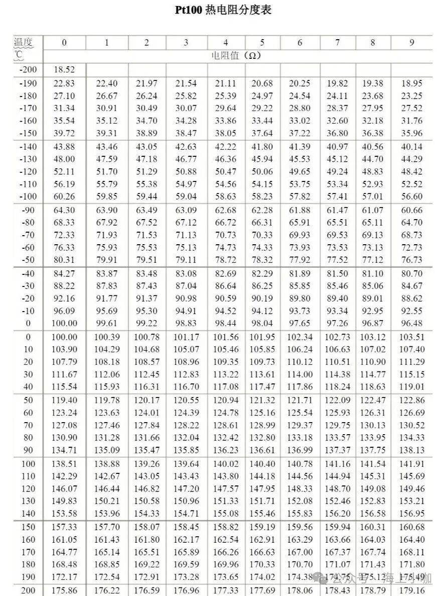
Common types of RTDs: Pt100. “Pt” represents platinum. “100” indicates that at 0°C, its nominal resistance value is 100 ohms. As temperature changes, its resistance value changes according to a very precise pattern (for example, around 0°C, for every 1°C increase, the resistance increases by 0.38Ω).
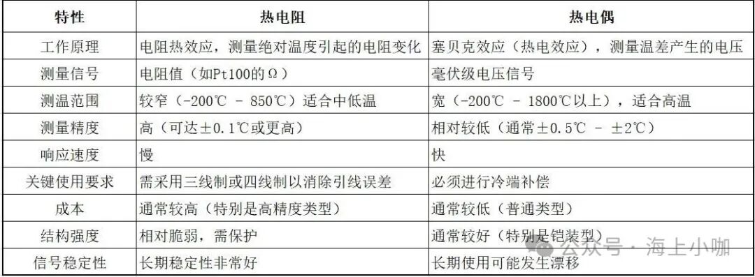
3. Core Differences Between Thermocouples and RTDs
2. How to Judge the Quality of Sensors
Judging the quality of sensors typically involves two methods: quick on-site assessment and precise measurement using instruments.
A. General Preliminary Inspection
1. Visual Inspection: Check for obvious physical damage to the sensor, such as broken protective sheaths, bending, severe corrosion, or water ingress in the junction box.
2. Wiring Inspection: Ensure that the terminal connections are secure, with no looseness, oxidation, or short circuits.
B. Using a Multimeter for Assessment
1. Judging the quality of thermocouples:
Step 1: Measure the resistance value
Use the resistance setting (Ω) on the multimeter. Measure the loop resistance by connecting the multimeter probes to the two terminals of the thermocouple.
• Normal condition: The resistance value should be very low, typically only a few ohms to a dozen ohms. The specific value depends on the length and material of the thermocouple.
• Abnormal conditions:
• Infinite resistance (open circuit): Indicates that the thermocouple or lead has broken. This is the most common fault.
• Resistance is zero or close to zero: May indicate a short circuit between the two electrodes inside the protective sheath.
• Abnormally high resistance: May indicate loose connections, oxidation, or partial breakage.
Step 2: Measure the voltage value (rough judgment)
• Set the multimeter to the millivolt DC voltage range (mV).
• Correctly connect the multimeter probes to the two terminals of the thermocouple.
• Heat the measurement end (hot junction): Gently heat the tip of the thermocouple (measurement end) with a lighter, soldering iron, or a cup of hot water. Note: Do not use a high-temperature flame directly, as it may damage or alter the metal material.
• Normal condition: During heating, the millivolt reading on the multimeter should steadily increase; when heating stops or cools down, the reading should steadily decrease. This indicates that the thermocouple responds to temperature changes and is fundamentally good.
• Abnormal conditions:
• No voltage at all (reading is 0): The thermocouple is damaged (open circuit or severely failed).
• No voltage change: The reading remains fixed regardless of heating, indicating thermocouple failure.
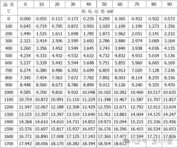
• Voltage value deviates significantly from the standard scale: Although the voltage changes, the value is severely inaccurate (for example, for a K-type thermocouple, at 200°C, the voltage should be about 8.1mV; if the measured value differs greatly, it indicates that the thermocouple has aged or deteriorated and needs replacement.
2. Judging the quality of RTDs:
Assuming the three terminals of the RTD are labeled A, B, and C, where B and C are shorted internally within the sensor. This is the key to judgment.
Step 1: Measure the resistance between the two shorted terminals (verify lead integrity)
• Operation: Use the multimeter probes to measure the resistance between terminals B and C.
• Normal value: The measured resistance should be very low, ideally close to 0Ω, usually less than 1Ω. This value is essentially the resistance of a single lead.
• Quality judgment:
• If the resistance is very low (e.g., 0.5Ω): Indicates that the two leads connecting B and C are intact.
• If the resistance is infinite (OL): Indicates that the lead to either B or C is broken, and the sensor or connecting wire is damaged.
Step 2: Measure the resistance between terminal A and the two shorted terminals (core judgment)
• Operation 1: Measure the resistance between terminals A and B, denoted as R_AB.
• Operation 2: Measure the resistance between terminals A and C, denoted as R_AC.
• Normal value:
• At ambient temperature, R_AB and R_AC should be approximately equal.
• For Pt100, at room temperature (about 25°C), the resistance should be around 110Ω. The calculation formula is: Rt = R0 * (1 + A*t + B*t²), with a simplified estimate of about 100Ω + 0.385Ω/°C * t. For example, at 25°C, 100 + 0.385*25 ≈ 109.6Ω.
• Quality judgment:
• If R_AB ≈ R_AC, and the resistance values conform to the theoretical values at the current ambient temperature: Indicates that the RTD and all three leads are in very good condition. This is the normal state.
• If R_AB and R_AC differ significantly:
• Indicates that one of the leads (connected to A or B/C) has an abnormal resistance, possibly due to poor contact or localized damage.
• If the difference is large, it may indicate a fault at the internal connection point.
• If both R_AB and R_AC are infinite (OL): Indicates that the connection from A to the RTD body is broken, and the RTD is damaged.
• If both R_AB and R_AC are close to 0Ω: Indicates that the RTD may have a short circuit internally, resulting in severe damage.
Step 3: Measure the insulation resistance to ground (optional, to check for moisture or contamination)
• Operation: Set the multimeter to the megaohm range (e.g., 20MΩ or 200MΩ), with one probe touching the metal casing of the RTD or any terminal, and the other probe touching the ground or the metal casing of the device.
• Normal value: The insulation resistance should be greater than 2MΩ, ideally as high as possible (e.g., tens of megaohms or even infinite).
• Quality judgment:
• If the insulation resistance is very low (e.g., less than 1MΩ): Indicates that the sensor is internally damp, dusty, or has conductive impurities, leading to reduced insulation performance and inaccurate measurements.
• If the insulation resistance is normal: Indicates that the sensor has good insulation.
3. Signal Changes Before and After Sensor Connection to PLC
Thermocouples
1. Before connection: The original “thermoelectric potential” signal
• Signal nature: Thermocouples operate based on the “Seebeck effect”; when there is a temperature difference between the measurement end and the reference end (cold junction), a very weak DC voltage signal, known as thermoelectric potential, is generated.
• Signal magnitude: This signal is extremely weak, typically only in the millivolt (mV) range. For example, for a common K-type thermocouple, for every 1°C change in temperature, the voltage changes by only about 40 microvolts (µV).
• Signal characteristics:
• Very weak: Highly susceptible to electromagnetic interference.
• Non-linear: The relationship between thermoelectric potential and temperature is not strictly linear.
• Requires cold junction compensation: Thermocouples measure the temperature difference between the measurement end and the reference end. To obtain the actual temperature at the measurement end, the accurate temperature of the reference end must be known. Before connecting to the PLC, this reference end is the ambient temperature at the thermocouple’s terminal, which is uncontrolled.
Thus, before connecting to the PLC’s terminal, the signal is a weak, easily disturbed, non-linear millivolt-level DC voltage.
2. After connection: How does the PLC process this signal?
The PLC cannot directly process such a weak and non-linear millivolt signal. Therefore, after the signal is connected to the PLC, it undergoes a series of processing:
Key component: The PLC’s special analog input module (commonly referred to as the “thermocouple module” or “RTD/TC module”)
This module performs the following tasks internally:
a. Cold junction compensation This is the most critical step. The module’s terminal integrates a high-precision temperature sensor (usually a thermistor or IC temperature sensor) to measure the temperature at the thermocouple wire connection terminal in real-time (i.e., the new reference end temperature, or cold junction temperature). The module’s internal processor then automatically compensates the original thermoelectric potential based on this measured cold junction temperature, converting it to the thermoelectric potential equivalent to 0°C at the cold junction.
b. Signal amplification Amplifies the compensated weak millivolt signal to a standard, easily processed voltage range, such as 0-10V.
c. Filtering Uses hardware filters to eliminate high-frequency noise interference from the signal.
d. Analog-to-digital conversion Converts the amplified and filtered analog voltage signal into a digital signal for the PLC’s CPU to read and process.
e. Linearization and scaling transformation The PLC module or PLC programming software contains standard tables for various types of thermocouples (K-type, S-type, J-type, etc.) that define the voltage-temperature relationship curves. It uses this table (or fitting formula) to convert the digital voltage value into the final temperature value (e.g., °C or °F). This process is called “linearization.”
Resistance Temperature Detectors (RTDs)
1. Before connection: The signal at the sensor end
At the terminal of an RTD (such as Pt100), the signal measured directly is the resistance value.
• Principle: The resistance value of an RTD changes with temperature (for example, Pt100 has a resistance of 100Ω at 0°C, and as temperature increases, the resistance increases).
• Characteristics: The resistance signal itself is very weak and is easily affected by the resistance of the wires (especially the length of the wires). If the RTD is directly connected to the PLC with long wires, the resistance of the wires will add to the measurement result, causing significant measurement errors.
2. Key aspect: Two main methods of signal transmission
To address long-distance transmission and anti-interference issues, in practical applications, the RTD signal is usually processed in two ways before reaching the PLC:
Method 1: Directly using the PLC’s RTD module (most common)
This is the most common practice. The PLC has dedicated RTD input modules.
• Signal during transmission: In this case, the signal remains the resistance value physically along the entire transmission path from the sensor to the PLC module.
• Role of the PLC module: The PLC’s RTD module is a highly precise “resistance measuring instrument.” It provides a constant current source that flows through the RTD, and then measures the voltage drop across the RTD to accurately calculate the resistance value based on Ohm’s law (R=U/I). Advanced RTD modules typically use three-wire or four-wire connections to automatically compensate for errors caused by lead resistance.
• Signal flow: RTD (resistance change) –> Wires (transmission of resistance signal) –> PLC’s RTD module
Method 2: Through a temperature transmitter
In cases of strong interference or very long transmission distances, temperature transmitters are used.
• Role of the transmitter: Temperature transmitters are usually installed near the RTD’s junction box or on a rail. They first read the resistance value of the RTD, then process and linearize it internally, directly converting it to a temperature value, and finally outputting this temperature value as a standard, interference-resistant current signal (most commonly 4-20mA).
• Signal during transmission: After passing through the transmitter, the signal from the transmitter output to the PLC is a 4-20mA analog current signal.
• Role of the PLC module: At this point, the PLC needs to use an analog input (AI) module (usually current input type) to receive this 4-20mA signal.
• Signal flow: RTD (resistance change) –> Temperature transmitter (converts resistance/temperature to 4-20mA current) –> Wires (transmission of current signal) –> PLC’s analog input (AI) module
3. After connection (into the PLC module):
• If directly connected to the RTD module, the PLC module perceives the resistance value (calculated from voltage and constant current source).
• If connected through the transmitter to the analog module, the PLC module perceives the current signal.

Click it, share, like, and check it out here