This article does not explain serial programming but discusses it from an application perspective. More often than not, products are ready, such as touch screens that need to communicate with controllers or PLCs. Ideally, once powered on, communication should be possible without too much operation and configuration.
The latter part of the article lists some related questions, but first, we need to understand what serial communication is, including RS-232, RS-485, and RS-422.


What is Serial Communication

Common serial communication usually refers to asynchronous serial communication.
Here, we need to talk about the difference between synchronous and asynchronous.
First, let’s discuss the concept of serial communication. What is the opposite of serial communication?
The opposite of serial communication is parallel communication. Data is generally transmitted in bytes, with one byte consisting of 8 bits. For example, in parallel communication, there are 8 wires, each representing a bit. A byte can be transmitted in one go, whereas in serial communication, data is transmitted over a single wire, meaning a byte requires 8 transmissions. Just like in the song by the Little Tigers, “String your heart with mine, and bake it a little…” Serial communication strings data together on one wire, hence the name.
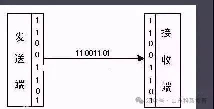
Asynchronous communication is contrasted with synchronous communication. Synchronous communication generally involves a clock signal for synchronizing data signals. For the receiver, synchronous communication is relatively simple. With a clock signal, every change in the high and low levels allows for data retrieval. The communication rate can be controlled by the sender or the master device. Communication speed is also generally much faster than serial communication. But why do many devices, such as screens and PLCs, not adopt this method and instead use serial communication?
In many devices, it is inconvenient to connect too many wires; for example, connecting 8 data lines is not convenient, nor is connecting a synchronous clock signal (which will be discussed later). Thus, asynchronous serial communication was born.
Relatively speaking, asynchronous serial communication only requires one wire to send data. In cases where speed requirements are not high, using one wire to send data brings great convenience and practical value.
Now, the question arises: how can we ensure that one wire can send normal data? In other words, how does the receiver know what data is being sent by the sender?
To send data correctly and receive the correct data, asynchronous serial communication must meet the following conditions:
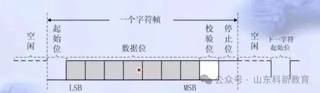
Both parties must agree on a protocol.
Perhaps at that time, the communication team discussed it this way:
Manager: I want to transmit data using one wire; you set a standard for me.
Developer: Sure.
Manager: With just one wire, how do I know when the data starts?
Developer: Well, with just one wire, we can default to a high level, so let’s have a start bit. When a low level is detected, it indicates that a byte of data is being sent. After the start bit, the least significant bit of the byte is transmitted.
Manager: But with just one wire, won’t the incoming data be interfered with and easily cause errors?
Developer: Sure, we can add a parity bit after the byte data. It can be odd parity, even parity, 1 parity, 0 parity, or no parity.
Manager: Hmm, that’s good. Since there’s a start bit, there should also be a stop bit, so let’s add a stop bit afterward.
Developer: …….
Manager: When transmitting a string of data, how does the other party know how to split the data? How do they interpret the data bits and parity bits based on time or frequency?
Developer: Let’s agree on a baud rate, defining how long each bit occupies time. This way, both parties can handle it according to this baud rate.
Manager: What’s a bit rate…
Developer: Boss, it’s baud rate.
Manager: I know, it’s the bit rate.
Developer: The baud rate refers to how many bits can be transmitted in one second, indicating how long each bit occupies. This solves the transmission problem.
Manager: What if during transmission, the data is too fast and causes misjudgment and can’t stop?
Developer: Then we can adjust the stop bit to be either 1 or 2 stop bits. That way, it can stop.
Manager: Hmm, sounds good. Let’s do it this way.
Thus, serial communication came into being.
In the parameters of serial communication, there are baud rate, data bits, stop bits, and parity bits to ensure the correctness and stability of serial communication. Of course, this is just one aspect of ensuring the correctness and stability of serial communication, and does not represent the correctness and stability of communication between devices.
Serial Communication Mainly Divided into RS-232, RS-485, and RS-422
Serial communication is mainly divided into RS-232, RS-485, and RS-422 communication methods.
RS-232:
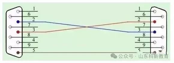
RS-232 communication mainly consists of three wires: RX, TX, and GND.
RX connects to TX, TX connects to RX, and GND connects to GND. This is relatively easy to understand because sending and receiving are handled by different wires, allowing for simultaneous data transmission and reception, which is called full duplex.
Here, let’s expand a bit: serial communication also has a function called full-featured serial communication, also known as standard serial. This is because when transferring data between two devices, some devices process data faster while others are slower. To ensure normal data transmission, several control pins are added on top of RX and TX. Originally, there were three wires: R, T, and G, but now there are nine pins, creating the DB9.
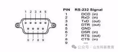
This originated from the time when computers were used, but the concept of the internet did not exist yet, and there was a need for communication between two computers. Hence, this was created.
In later devices, many controllers, human-machine interfaces, PLCs, etc., use serial communication without using standard serial but directly using the three wires RX, TX, and GND for communication.
But why mention this? Because while many devices use this method, there are still a few devices that retain the functionality of standard serial communication. This is why you might encounter situations where communication works fine on a computer but fails when switching to a touch screen. Many touch screens only use RX, TX, and GND for communication, while some retain the standard serial function, causing issues.
RS-485:
RS-485 was designed to solve the distance issue of RS-232 communication. I won’t go into the principles and such. In short, RS-232 communication has a limited distance. RS-485 mainly transmits using a differential signal, requiring only two wires, + and -, or A and B. The differential level signal between A and B serves as the data signal for transmission. The question arises: does this mean there’s no RX and TX concept? Yes, sending and receiving cannot be separated. Both sending and receiving rely on these two wires, meaning you can only send or receive at one time, which is the concept of half duplex. This is significantly less efficient than RS-232. It’s like a walkie-talkie; someone usually says “over” after speaking to ensure the current speaker has finished and is waiting for a response.
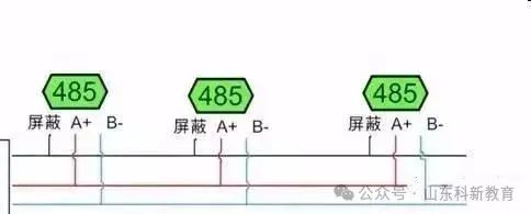
RS-485 sacrifices the full duplex efficiency of RS-232 to achieve longer transmission distances. So, is there a way to retain the full duplex of RS-232 while also achieving the long-distance transmission like RS-485? Thus, RS-422 was introduced.
RS-422:
RS-422 is sometimes labeled as RS-485-4, while RS-485 is labeled as RS-485-2. What’s the difference? It’s just for memory. RS-485-2 means 2 wires, while RS-485-4 means 4 wires.
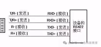
RS-422 divides the RX of RS-232 into two wires, RX+ and RX-, and divides the TX into TX+ and TX-. This allows for simultaneous sending and receiving while maintaining a longer transmission distance like RS-485. However, despite these advantages, it is not widely used. My personal answer and understanding is that there are just too many wires. Especially for someone like me who dislikes wiring, more than three wires can be overwhelming. When it comes to communication, having to connect so many wires, including TX, RX, positive, and negative, can be cumbersome.
In many device communications, it is generally a question-and-answer style, so the advantages of full duplex communication of RS-232 are not fully utilized. It’s like making a phone call; even though both parties can speak simultaneously, if they both talk at once, it’s hard to understand anyone. Especially in a master-slave communication scenario with multiple slaves, RS-485 is much more convenient since everyone connects to just two wires, with all + connected together and all – connected together. If RS-422 were to be used in a master-multiple-slave setup, the wiring would be more complicated, and troubleshooting communication issues would be more challenging.
Alright, that covers the basics of serial communication. Now, let’s address the questions mentioned earlier.
1. Why can a computer using USB to serial communicate with a device, but when switched to a screen, it fails to communicate?
1) It’s possible that the USB to serial converter on the computer is using the standard serial function, which means that besides RX, TX, and GND, it also uses other pins. For example, with Omron PLCs and Mitsubishi PLCs, certain pins need to be shorted during actual communication with the screen.
2) When the computer communicates with the controller or PLC, it scans the baud rate parameters adaptively, while the screen’s communication parameters may not match those of the device. In Mitsubishi, Keyence, and other PLCs, the baud rate may vary during communication interaction.
3) It could also be due to incorrect wiring. Some DB9 connectors require male and female connectors. If not careful, one might connect TX to TX and RX to RX, which is something to watch out for.
4) Additionally, sometimes a serial assistant may be used to send test data to communicate with the controller, but some serial assistants may not function correctly with odd/even parity; this needs to be noted.
2. Why can screen A communicate with the device, but screen B cannot?
1) First, check if the wiring is correct, and whether RX and TX are compatible.
2) Ensure that the ground wire is connected.
3) Besides RX, TX, and GND, check if there are other pins that need to be shorted.
4) Verify that the communication protocols are consistent and complete, and that the baud rates match.
3. Why did it work without a ground wire before, but now it requires one?
This question is similar to the previous one. Some devices use isolated power supplies. Previously, communication without grounding could work because the ground was already connected in another loop. However, if the new device has an isolated power supply, the grounds of the two devices may be isolated, requiring the ground wire to be connected in serial communication. I have personally experienced this with a customer who claimed their device could not communicate. After receiving a photo, I noticed the ground wire was not connected. I explained to him that it had to be connected.
4. One device is RS-232, and the other is RS-422. What should I do without a conversion device? (Simple method to convert between RS-232 and RS-422)
I have encountered this situation where a customer’s device communicates via RS-422, but I only have RS-232 devices for testing. Therefore, I need to convert RS-422 to RS-232 for communication. As mentioned earlier, RS-422 and RS-232 wiring is different because both are full duplex, with separate receiving and sending paths, while RS-422 transmits using a differential signal.
Connect RS-422’s Rx+ to RS-232’s TX, RS-422’s RX- to RS-232’s GND. Connect RS-422’s TX+ to RS-232’s RX, and RS-422’s TX- to RS-232’s GND.
This way, when the RS-422 device sends data, it can reach the RX of RS-232. When RS-232’s TX sends data, the differential signal formed by TX and GND can be received by RS-422.
5. Communication is stable with RS-232 and RS-485, but becomes unstable after converting RS-232 to RS-485?
The main difference between RS-232 and RS-485, from a communication principle perspective, is the full duplex versus half duplex distinction. However, at the application layer, sending and receiving data does not concern whether it’s full duplex or half duplex.
However, RS-485 does need to be managed. Since it’s half duplex, it’s crucial to ensure that only sending or receiving data occurs on the line. If both happen simultaneously, data will collide. Therefore, the solution is for the master device, which actively commands, to strictly control the rhythm of sending data commands.
Of course, some RS-232 to RS-485 devices are well-designed to optimize this, but the master still needs to control it, often by slowing down the communication rate (not adjusting the baud rate).
6. Why does communication work fine when connecting each device individually with RS-485, but becomes unstable when connecting multiple slaves together?
This falls under the instability factors of RS-485 communication.
7. What’s a good way to allow two screens or two master stations to access a Modbus device via RS-485?
In RS-485 communication, it’s generally one master to multiple slaves. However, some customers want to use two screens to access a Modbus device. Currently, there’s no good solution.
8. What should be noted regarding the weaknesses of serial communication?
Speaking of the weaknesses of serial communication, it’s a long story, but let’s keep it short.
1) Signal interference issues.
It is recommended to use shielded cables and ensure strict wiring, such as grounding. In some RS-485 communications, consider adding terminal resistors for matching. For RS-232, avoid overly long cables. In terms of communication protocols, try to avoid long message data communications.
2) Baud rate matching issues.
Some devices have errors in calculating baud rates, especially some controllers due to different oscillators. Therefore, at certain baud rates, like 9600, there can be errors. What is the impact of these errors? The receiver calculates the duration of each bit based on time. If a message is too long, there will be cumulative error issues, causing misalignment over time. This is also one of the reasons for instability in serial communication; thus, it’s advisable to avoid sending overly long data packets.
3) In situations where interference may occur, consider using odd or even parity in some cases. While the likelihood of errors is low, interference can occur, and adding parity can at least filter out erroneous messages. It’s better than having no parity and not knowing if the data is wrong. Alternatively, try to use protocols with built-in parity to prevent data errors.
4) Serial communication is inherently slow, so lower your expectations for data response.
Because serial communication is slower than Ethernet. Moreover, serial communication cannot be processed in a multi-threaded manner like a CPU. Since there’s just one port and one wire for data transmission, even if your application uses multi-threading to handle data, at the lowest level, there’s only one port for transmitting one bit or one byte at a time. Some customers use a baud rate of 9600 but expect a certain amount of data to be responded to within a certain number of milliseconds.
However, serial communication should be approached realistically, so correctly understanding serial communication is very helpful for applications, development, and communication.
Why not use synchronous communication?
As mentioned earlier, synchronous communication relies on a clock signal. This raises the question of who initiates the clock signal. In synchronous communication, a master device often initiates the clock signal to read data from the slave modules. In practice, there are screens reading data from PLCs and screens reading data from other screens. Purely from the perspective of asynchronous serial communication, there is no master-slave relationship; both parties are equal roles, able to send and receive information to each other. Synchronous communication is generally applied when a CPU reads some modules, with the CPU initiating the clock signal, such as reading from an SD card module via SPI, as well as some sensor modules.
Source: This article is adapted from the internet; copyright belongs to the original author. If there are any copyright issues, please contact us to delete it promptly. Thank you!

Scan to Follow
WeChat ID|13615417996
Follow the left QR code to get it for free
[Siemens Data Collection]