In the context of industrial automation and the development of the Internet of Things, data transmission protocols are the cornerstone of all operations. Among them, the Modbus protocol has become one of the most popular communication protocols in the industrial field due to its openness, wide application, and simplicity. This article will provide an in-depth explanation of the concept, advantages, modes, common functions, and practical experiences of Modbus, helping you quickly grasp the core content of the Modbus protocol.
What is Modbus?

Modbus was designed by Modicon (now Schneider Electric) in 1979 as a protocol specifically developed for communication between industrial devices. Essentially, Modbus is an application layer protocol aimed at defining a unified message structure that allows various controllers or devices to understand and communicate with each other. It is important to note that Modbus itself does not define physical layer specifications, so it can operate over various interfaces and transmission media, such as RS-232, RS-485, and Ethernet (TCP/IP).
Core Features of Modbus
- 1.Openness: Modbus is a completely open-source protocol with no copyright requirements, meaning that almost all manufacturers can easily integrate it.
- 2.Wide Compatibility: It supports various physical interfaces (such as RS-485) and transmission media (such as fiber optics, wireless networks, etc.).
- 3.Simple: The message structure of the Modbus protocol is compact, easy to read, and efficient, allowing engineers and developers to quickly get started.
- 4.Universality: From programmable logic controllers (PLCs) and sensors to industrial gateways, almost all devices in industrial environments support Modbus.
Due to its flexibility and efficiency, Modbus has become the preferred communication bridge in industrial control sites.
Communication Modes of Modbus
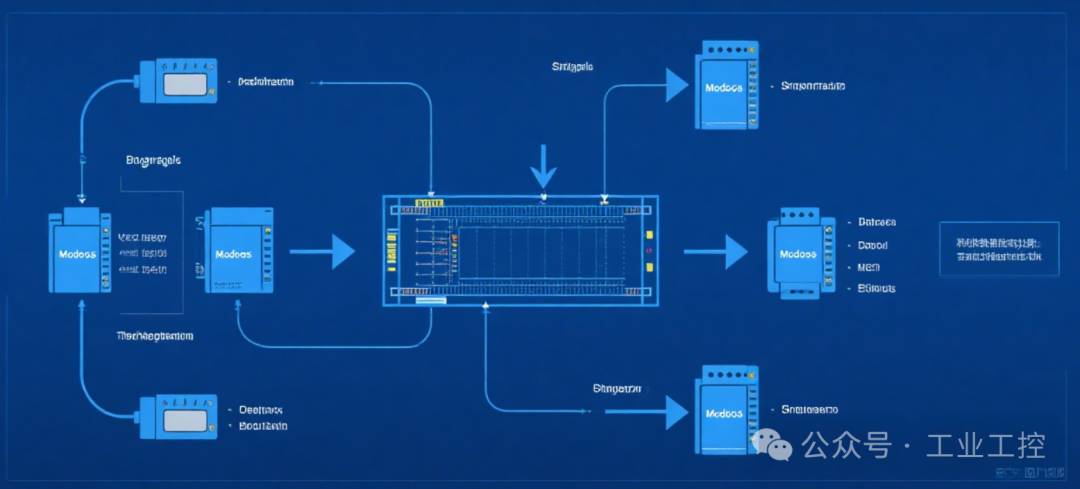
The Modbus protocol defines two main communication modes: RTU (Remote Terminal Unit) mode and ASCII mode, which cater to different transmission needs.
Modbus RTU
RTU mode is in binary format, transmitting data with a compact frame structure, suitable for bandwidth-limited communication scenarios (such as serial communication). Its messages include a complete data verification mechanism (16-bit CRC check), ensuring high reliability of data transmission.
Features:
- High communication efficiency, with each message occupying fewer bytes.
- Uses a fixed time interval (3.5 byte periods) to distinguish between frame start and end.
For example, at a baud rate of 9600, one character occupies 11 bits, so a 3.5 byte period corresponds to an interval of 4.01 milliseconds.
Modbus ASCII
ASCII mode uses human-readable ASCII code format, which is very convenient for debugging, but is less efficient in communication compared to RTU mode. Each message starts with the **“:” character** and ends with carriage return and line feed (CR LF), using LRC (Longitudinal Redundancy Check) to verify data integrity.
Features:
- Lower data transmission efficiency, but easier for debugging and identification.
- In practical applications, Modbus devices primarily use RTU, with ASCII as a secondary option.
Modbus Data Model and Function Codes
Modbus classifies and manages data by dividing the device’s storage space into four major storage areas, simplifying system integration significantly.
Four Major Storage Areas
| Storage Area Type | Starting Address | Purpose | Data Operation |
|---|---|---|---|
| Output Coils (Coil) | 00001 | Output Status (Binary) | Read/Write |
| Input Coils | 10001 | Input Status (Binary) | Read-Only |
| Input Registers | 30001 | Analog Value Collection (Read-Only Registers) | Read-Only |
| Holding Registers | 40001 | Holding Variables (Read/Write Registers) | Read/Write |
Modbus operates these storage areas through function codes (Function Code). For example:

- Read Coils (Function Codes 01 and 02): Used to read the status of a segment of coils, returning the on/off status of the selected coils.
- Read Registers (Function Codes 03 and 04): Read the analog input values collected through AD or the values of holding variables.
- Write Coils or Registers (Function Codes 05 and 06): Can directly control device operation.
Example: Modbus Data Read/Write Process
To better understand Modbus read/write operations, we will analyze an example of reading a holding register (Function Code 03):
Sending Message Format for Reading Holding Registers
Data Sent
01 03 00 6B 00 02 76 87
- 01: Device address, indicating a command sent to slave device 1.
- 03: Function code, indicating reading a holding register.
- 00 6B: Starting address of the register (107).
- 00 02: Number of registers to read (2 registers).
- 76 87: CRC check code, verifying the legality of the entire data frame.
Return Message
01 03 04 02 2B 01 06 4E 34
- 01: Slave address.
- 03: Function code.
- 04: Number of return bytes, indicating there are 4 bytes in the data area.
- 02 2B 01 06: Values of the two registers (40108=022B, 40109=0106).
- 4E 34: CRC check code.
Through similar analysis, users can verify the correctness of messages and debug the communication process at any time.
Applications of Modbus in Practice
In practical scenarios, Modbus is almost ubiquitous. From smart sensors and instruments to industrial automation control systems, it serves as a communication bridge, playing a crucial role in data collection and command execution. Here are several classic use cases:
- 1.PLC and HMI Connection: Exchanging production line status, alarm signals, and real-time data via Modbus.
- 2.Sensor Data Collection: Industrial sensors upload environmental temperature, humidity, pressure, and other data to servers via Modbus.
- 3.Multi-Device Networking: Utilizing the multi-point communication capability of RS-485 bus to form a unified control network of Modbus devices.
These practical cases demonstrate that Modbus has become a core driving protocol for building industrial IoT due to its openness and high compatibility.
Practical Recommendations
To better learn Modbus, the following three tools are recommended:
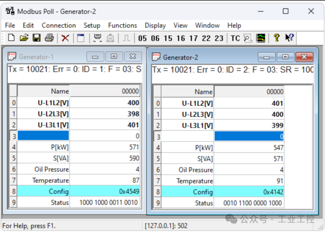
- 1.Modbus Poll: Simulates a master station sending and receiving Modbus data.
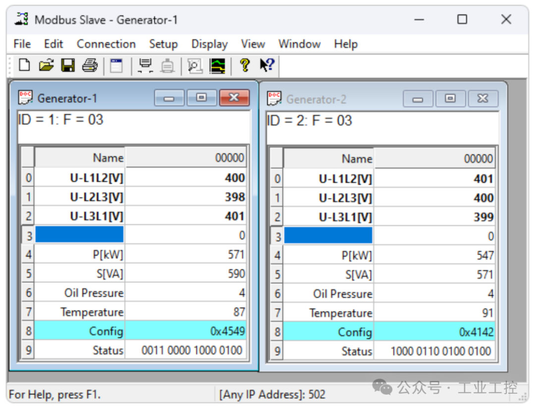
- 2.Modbus Slave: Simulates slave devices for debugging the master station.
- 3.Virtual Serial Port Driver (VSPD): Creates virtual serial ports on a PC to accelerate the debugging process.
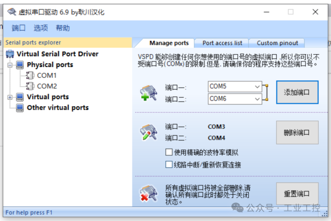
Beginners can understand the working logic of data frames and improve practical skills through simulated environments.
The reason Modbus continues to dominate the industrial communication field is due to its openness, universality, and simplicity. Whether you are an engineer, product developer, or IT technician, mastering the Modbus protocol can pave the way for building efficient and reliable industrial systems.
Recent Popular Articles:
| Finally, someone has clarified RS485 and ModbusFinally, someone has explained RS485 clearlyAwesome! Quickly resolve serial port debuggingData big screen yyds! Supports 30+ types of charts, amazingyyds! Open-source MES written in C#, amazing! |