If we compare a pure electric vehicle to a running beast, the motor is the heart, and the motor controller is the “nervous center” that precisely regulates the heartbeat. Hidden deep within the vehicle, it directly determines the smoothness of power output, energy efficiency, and driving safety—this article will break down the structural logic of this core component, helping you understand how it smoothly converts electrical energy into driving force.
External Structure of the Motor Controller:
① Busbars (DC+, DC-) connected to the power battery;
② Three-phase lines U, V, W connected to the drive motor;
③ Connectors connecting to internal sensors of the drive motor;
④ Inlet and outlet pipes for coolant;
⑤ Low-voltage connectors connecting to the MCU main control board;
Internal Structure of the Motor Controller:
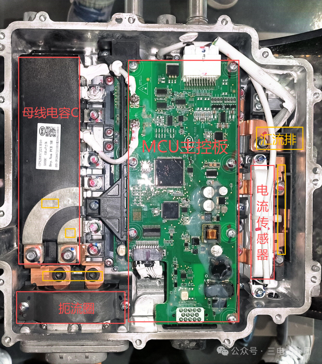
① Bus Capacitor C: When mentioning bus capacitors, you should think of three points: it stores and releases electrical energy (supplying power to the MCU main control board); it is in parallel with the power battery; the pre-charging process in the high-voltage power-up sequence of pure electric vehicles refers to the need to charge it.
② Choke: It stabilizes current, suppresses electromagnetic interference, and protects the circuit.
③ MCU Main Control Board: It receives signals from the internal resolver sensor and temperature sensor of the drive motor (signals for rotor position, speed, rotation direction, and stator coil temperature); it calculates the current value on the U phase line based on the current values detected on the V and W phase lines; it can interact with the driver board.
④ Busbar: It gathers current and distributes electrical energy.
⑤ Current Sensor: It detects the current on the V and W phase lines; once the current exceeds the limit, it immediately triggers a protection mechanism to prevent damage to power devices like IGBTs.
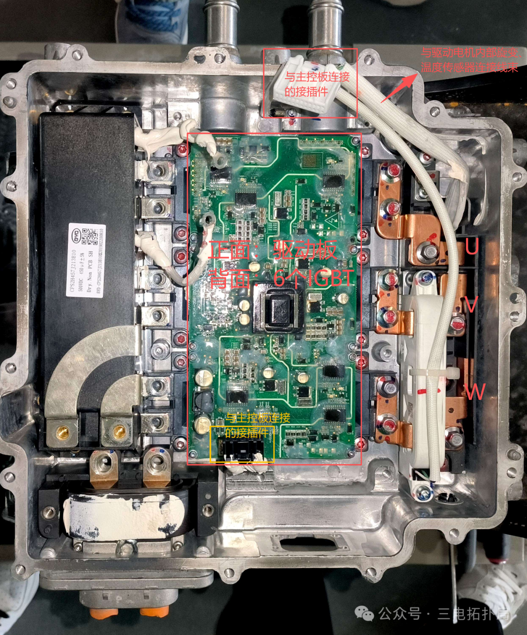
⑥ Driver Board: The weak electrical signals (a few volts) from the main control chip cannot directly drive the IGBT; the driver board amplifies the voltage/current through an amplification circuit to meet the switching requirements of the IGBT; it precisely matches the switching timing of the six IGBTs in the three-phase full-bridge topology, ensuring stable three-phase AC waveform output; it uses opto-isolation/magnetic isolation technology to achieve strong-weak electrical isolation, avoiding high-voltage circuit interference with the main control chip while monitoring the IGBT status and quickly shutting down for protection in case of anomalies.
⑦ Six IGBTs: They receive PWM (Pulse Width Modulation) signals from the MCU main control chip, rapidly switching on and off to precisely adjust the frequency and amplitude of the output AC, thereby controlling the motor’s speed and torque.
The following images show the physical motor controller disassembled by students:
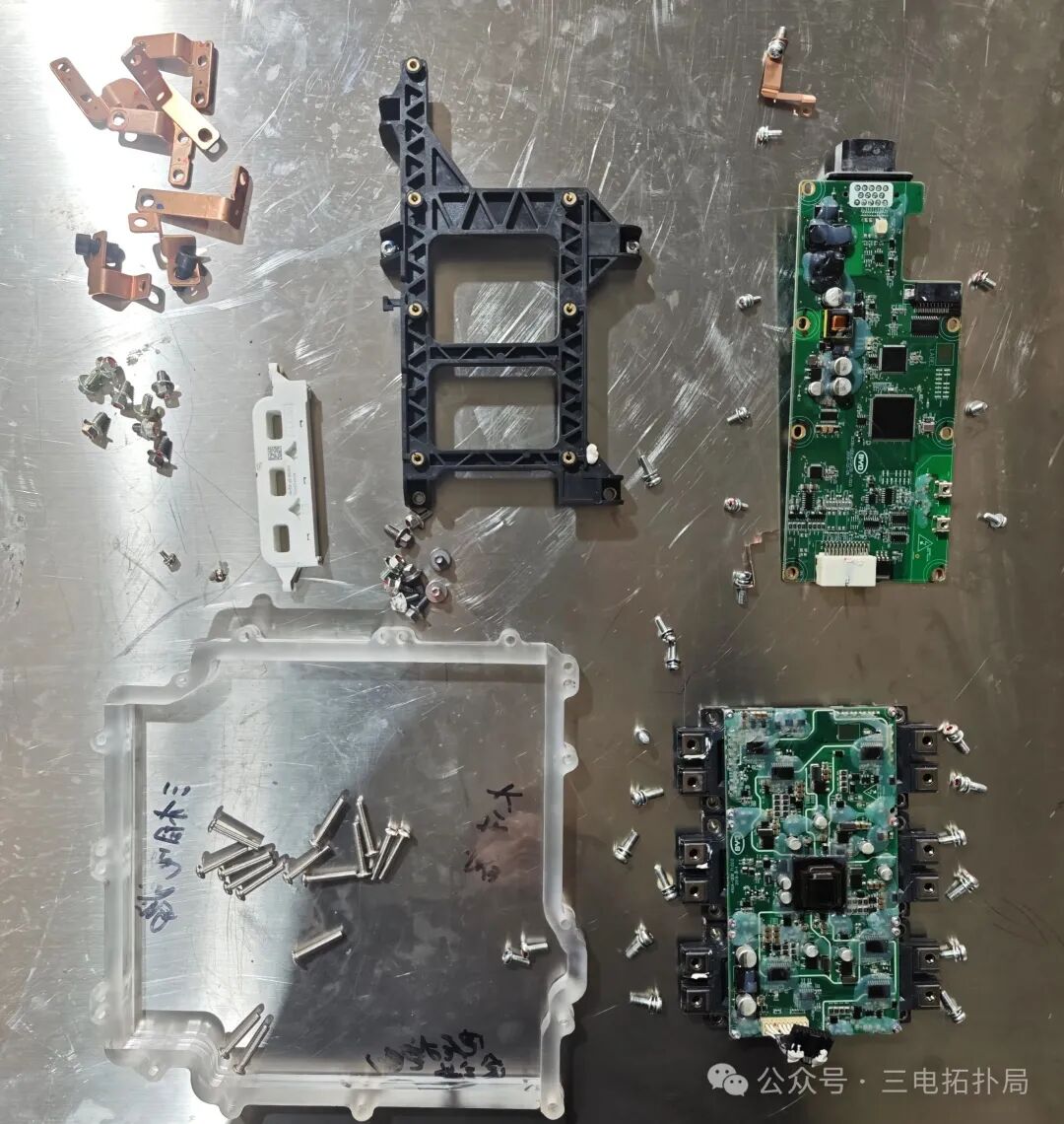
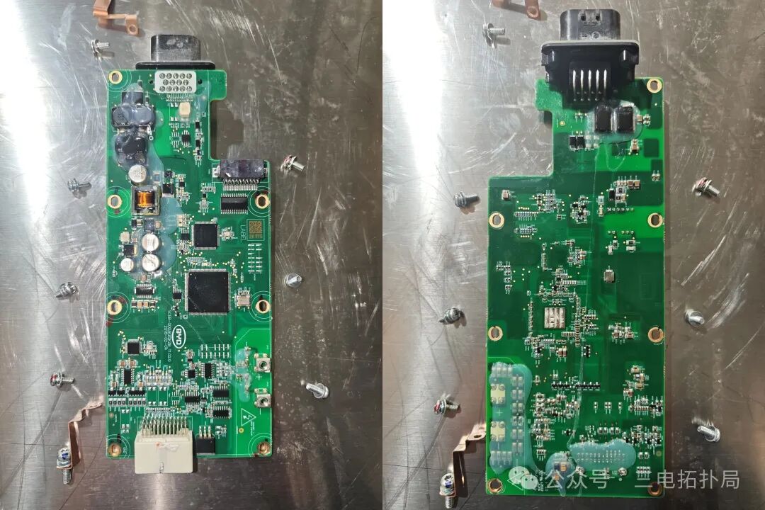 MCU main control board front and back
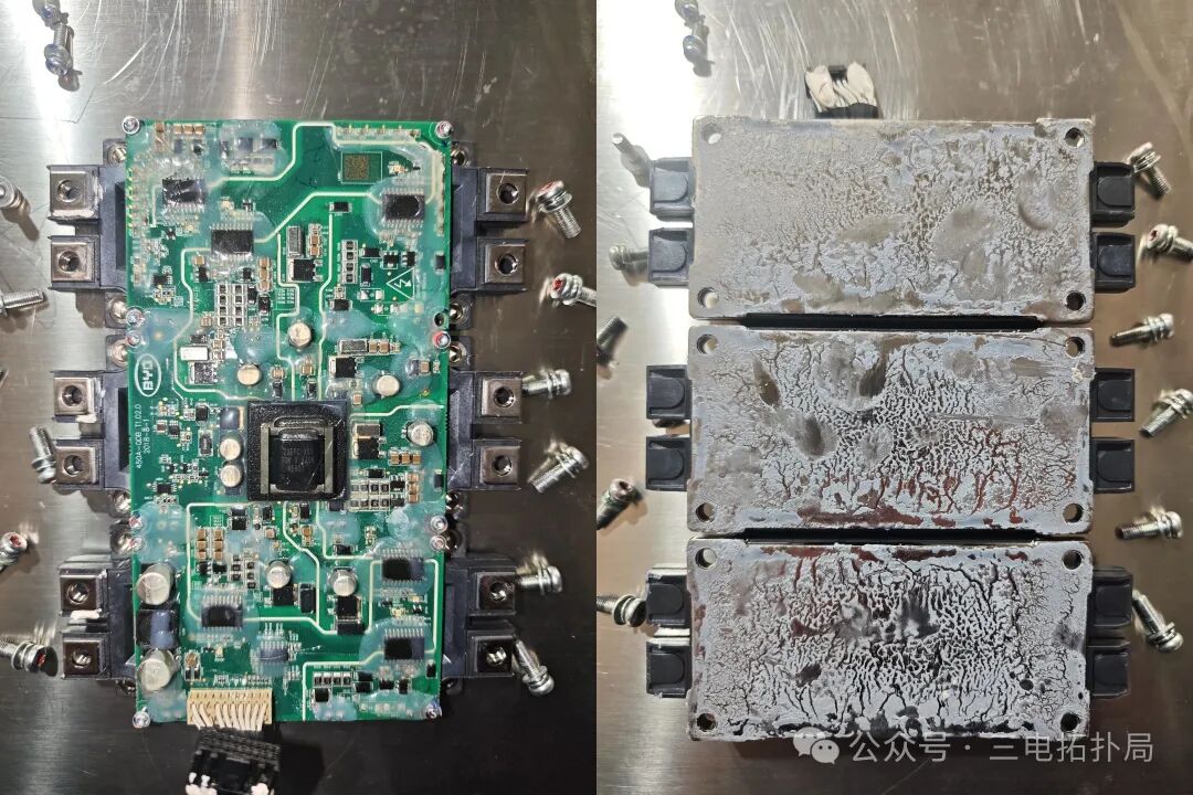 Driver Board 6 IGBTs
As we all know, the motor controller converts the high-voltage DC from the power battery into three-phase AC to drive the motor. How is this principle achieved?
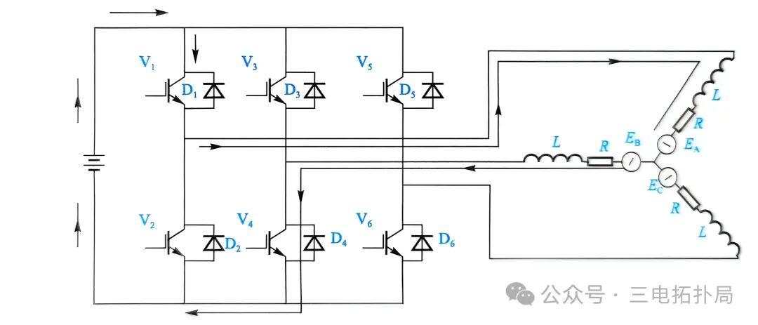
The working principle is as follows:
First Stage: With the motor rotor at 0° as the starting point, the driver board first turns on V1 for 120° electrical angle, during which V4 is turned on for 60° electrical angle. The current path is: EV+→V1→U phase (A phase)→V phase (B phase)→V4→EV−. Then V4 is turned off, and V6 is turned on for 60° electrical angle, with the current path:EV+→V1→U phase(A phase)→W phase (C phase)→V4→EV−. At this point, the motor rotor rotates 120°, with a distance of 120° from the starting point.
Second Stage: With the motor rotor at 120° as the second starting point, V3 is turned on for 120° electrical angle, during which V2 is turned on for 60° electrical angle. The current path:EV+→V3→V phase(B phase)→U phase(A phase)→V2→EV−. Then V2 is turned off, and V6 is turned on for 60° electrical angle, with the current path:EV+→V3→V phase(B phase)→W phase(C phase)→V6→EV−. At this point, the motor rotor rotates 120°, with a distance of 240° from the starting point.
Third Stage: With the motor rotor at 240° as the third starting point, V5 is turned on for 120° electrical angle, during which V2 is turned on for 60° electrical angle. The current path:EV+→V5→W phase(C phase)→U phase(A phase)→V2→EV−. Then V2 is turned off, and V4 is turned on for 60° electrical angle, with the current path:EV+→V5→W phase(C phase)→V phase(B phase)→V4→EV−. At this point, the motor rotor rotates 120°, with a distance of 360°, completing a full circular motion.
From the precise transmission of weak electrical commands to the efficient conversion of strong electrical energy, every structure of the motor controller safeguards the “conversion of electrical energy into power”—it is hidden within the vehicle but supports the core strength of pure electric travel. After reading this breakdown, I believe you have a clearer understanding of the “nervous center” of electric vehicles.