A multimeter is an electrical tool that can be used by engineers, beginner electricians, seasoned electricians, and even ordinary residents. But do you really know how to use a multimeter? Today, Xiao 7 will introduce the multimeter from four aspects: [Brands of Multimeters], [Get to Know Multimeters in One Minute], [Must-See! Mnemonics for Using Multimeters], and [Ten Tips for Using Multimeters]. After reading this article, you will definitely have a thorough understanding of how to use a multimeter!01Brands of Multimeters
There are hundreds of brands and models of digital multimeters available in the market, with dozens of common domestic and international models. Which one are you using?

02Get to Know Multimeters in One Minute
1. The common types of multimeters are analog and digital:
The analog multimeter is a multifunctional measuring instrument that uses a mechanical dial as its core component, and the measured value is read from the pointer on the dial;
The digital multimeter displays measured values directly in numerical form on an LCD screen and often includes some voice prompt functions.
2. Classification by appearance:
There are desktop, clamp-type, handheld, and pocket-sized models.

3. Comparison of advantages and disadvantages:
The reading accuracy of analog multimeters is slightly lower than that of digital multimeters, but the process of the pointer’s movement is more intuitive and obvious. Its speed and amplitude can sometimes objectively reflect the size and direction of the measured value.
Digital instruments have high sensitivity, high accuracy, clear display, strong overload capacity, are easy to carry, and are simpler to use.
 Analog Multimeter
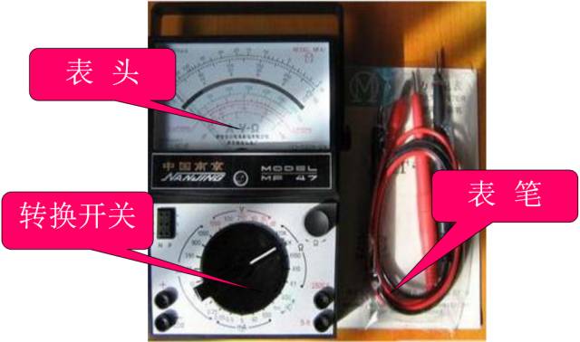
There are many types of analog multimeters, but their basic structure is similar. The structure of an analog multimeter mainly consists of three parts: the meter head, the selector switch (also known as the range switch), and the measurement circuit.
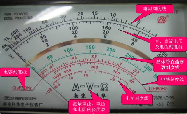
The meter head: is the display device for measurement; the meter head of a multimeter is actually a sensitive ammeter.
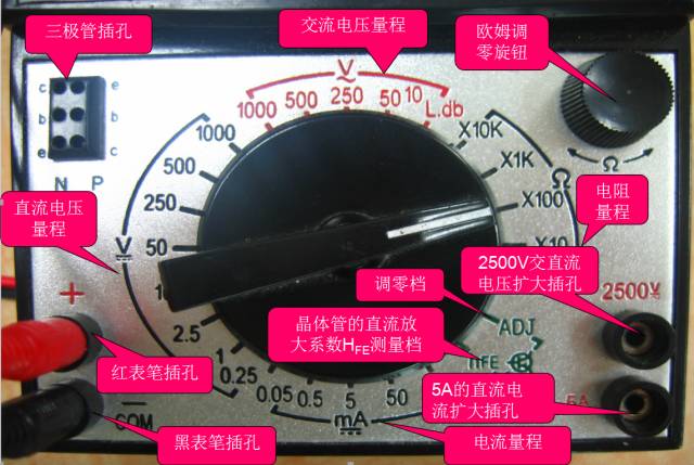
The selector switch: selects the type and range (or multiple) of the measured electrical quantity.
The measurement circuit: converts the measured electrical quantities of different properties and sizes into direct current that the meter head can accept.
Thehead
Selector switch
Cautions for Using Analog Multimeters
When using:
(1) Must be placed horizontally to avoid errors.
(2) Do not collide with hard objects or drop it on the ground.
(3) Do not touch the metal parts of the probes with your hands.
(4) When measuring a certain electrical quantity, do not change the range while measuring, especially when measuring high voltage; otherwise, it may damage the multimeter.
If you need to change the range, disconnect the probes first, then change the range and measure again.
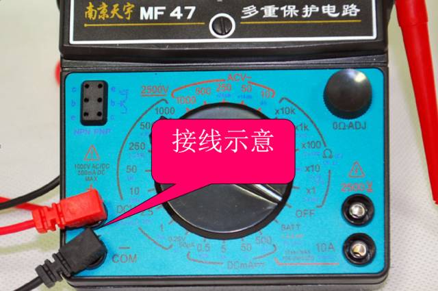
Correct Wiring:
1. The red probe should be connected to the “+” polarity socket, and the black probe should be connected to the “—” or “*” or “COM” polarity socket.
2. When measuring direct current, pay attention to the positive and negative polarities to avoid reversing the pointer.
3. When measuring current, the meter should be connected in series in the circuit being measured; when measuring voltage, the meter should be connected in parallel across the circuit being measured.
4. When measuring transistors, remember that the red probe should connect to the negative terminal of the internal battery of the multimeter; the black probe should connect to the positive terminal of the internal battery.
Correctly Selecting Measurement Ranges
1. When measuring voltage, the selector switch should be set to the corresponding voltage range; when measuring current, it should be set to the corresponding current range, etc.
2. When selecting current or voltage ranges, it is best to keep the pointer at more than two-thirds of the scale; when selecting resistance ranges, it is best to keep the pointer at the middle of the scale.
3. When measuring, if you are unsure of the range of the measured value, first set the selector switch to the maximum range, then gradually reduce it to an appropriate range based on the degree of deflection of the pointer.
After Use:
(1) After using the multimeter, if there is no empty position, set the range selector switch to the highest AC voltage range; if there is an empty position (“*” or “OFF”), it should be set to that position.
(2) If the multimeter will not be used for a long time, the battery inside should be removed to prevent the battery electrolyte from leaking and corroding the internal circuit.
Digital Multimeter
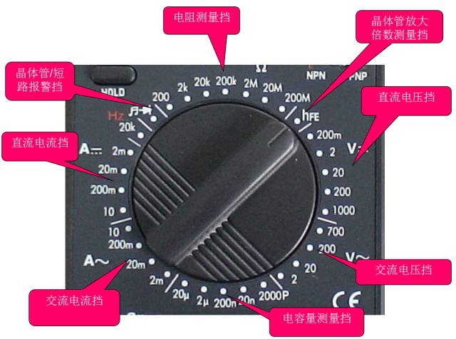
Selector dial
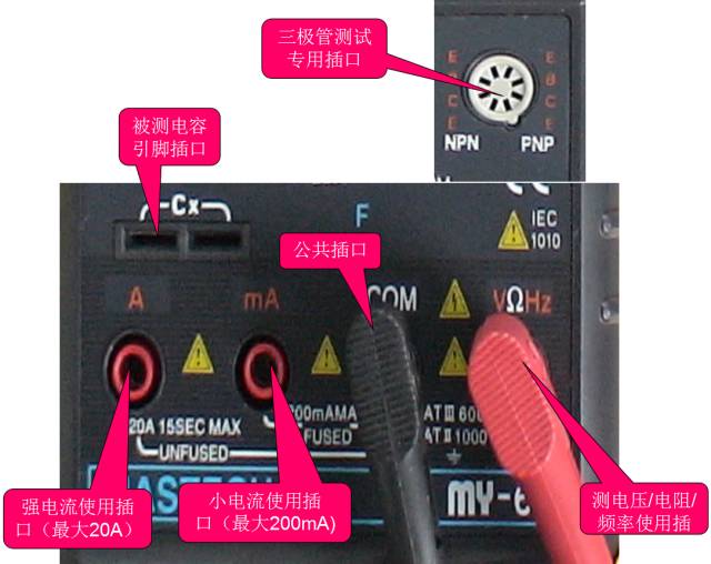
Sockets
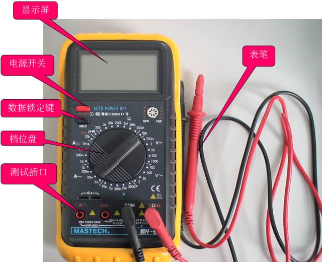
Cautions for Using Digital Multimeters
a. If you cannot estimate the size of the voltage or current to be measured in advance, you should first set it to the highest range and measure once, then gradually reduce the range to an appropriate position based on the situation. After measuring, set the range switch to the highest voltage range and turn off the power.
b. When full-scale, the meter only displays the digit “1” at the highest position, and other positions disappear. At this time, you should select a higher range.
c. When measuring voltage, the digital multimeter should be connected in parallel with the circuit being measured. When measuring current, it should be connected in series with the circuit being measured; when measuring direct current, polarity does not need to be considered.
d. When mistakenly using the AC voltage range to measure DC voltage, or mistakenly using the DC voltage range to measure AC voltage, the display will show “000” or low digits will fluctuate.
e. It is forbidden to change the range when measuring high voltage (above 220V) or large current (above 0.5A) to prevent arcing and burning the switch contacts.
f. When the display shows ” ” or “BATT” or “LOW BAT”, it indicates that the battery voltage is below the operating voltage.
03 Mnemonics for Using Multimeters
First check the range before measuring; do not measure without checking.
Every time you pick up the probes to prepare for measurement, be sure to double-check that the measurement category and range selector switch are set correctly. For safety, this habit must be cultivated.
Do not change the range during measurement; switch to the empty position after measuring.
You must not arbitrarily turn the selection knob during measurement, especially when measuring high voltage (such as 220V) or large current (such as 0.5A) to avoid arcing and damaging the switch contacts. After measuring, set the range selector switch to the “•” position.
The dial should be horizontal, and the reading should be aligned.
When using a multimeter, it should be rotated horizontally, and the line of sight should be directly aligned with the pointer when reading.
The range should be appropriate, and the pointer should deflect more than half.
When selecting a range, if you cannot estimate the size of the measured value in advance, you should choose a larger range, then gradually switch to a smaller range based on the deflection angle until the pointer deflects to about two-thirds of the full scale.
Do not measure resistance with power on; discharge capacitors before measuring.
It is strictly forbidden to measure resistance while the circuit is powered. When checking large capacitors on electrical devices, be sure to discharge the capacitors before measuring.
Set the zero point before measuring resistance; zero point adjustment is required when changing ranges.
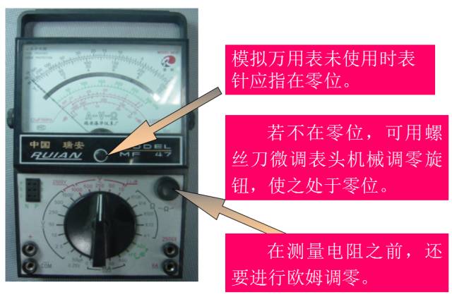
When measuring resistance, set the selector switch to the resistance range, short-circuit the two probes, and turn the “Ω” zero potentiometer to make the pointer point to zero ohms before measuring. Each time you change the resistance range, you should readjust the ohm zero point.
Remember to connect the black probe to the negative; the black probe connects to “+” inside the meter.
The red probe is positive, and the black probe is negative, but in the resistance range, the black probe connects to the positive terminal of the internal battery.
When measuring current, it should be connected in series; when measuring voltage, it should be connected in parallel.
When measuring current and voltage, pay special attention that the polarities of the red and black probes must not be reversed, and you must develop the habit of using one hand for safety.
04 Ten Tips for Using Multimeters1. Method for Measuring Leakage with a Multimeter
Use the continuity setting of the multimeter to measure between the ground and the part of the circuit being measured. If the meter shows a resistance value, it indicates that it is not insulated.
However, in reality, when measuring leakage, you should use a megohmmeter, also known as a shake meter. Because the voltage across the probes of the multimeter during measurement is very low, generally not exceeding 9V, it cannot break down the gap for leakage. A megohmmeter can reach over 1000V. Connect the multimeter leads to the corresponding terminals for measuring AC voltage, then use one probe to measure the neutral wire or ground, and the other probe to measure the suspected leakage point. If the reading is 0, it indicates no leakage and no voltage! If it shows 220 or any voltage above 36V, it indicates leakage and is unsafe!
Use the resistance setting of the multimeter at 200M range to measure insulation resistance, first determine which wire is leaking or which two wires are shorted.
Methods are as follows:
Measure the insulation resistance between the live wire and neutral wire, measure the insulation resistance between the live wire and ground, and measure the insulation resistance between the neutral wire and ground. If shorted, the insulation resistance will be basically zero.
Knowing which wire has leakage, you can use a segmental searching method to gradually narrow down the fault range.
Or use the elimination method, conducting power tests section by section after separating the lines.
2. How to Distinguish Between Neutral and Live Wires with a Multimeter
Generally speaking, to identify the neutral and live wires in the mains, it is not possible to use a low-voltage test pen. Can a multimeter distinguish between live and neutral wires?
The answer is yes; the method is as follows:
Set the multimeter’s range switch to the AC voltage 250V or 500V range. Connect the black probe to a wet ground, such as a water pipe or moist ground, and touch the red probe to the power line or socket. The voltage value indicated by the multimeter will be higher for the live wire and lower or zero for the neutral wire.
3. How to Measure Neutral and Live Wires with a Digital Multimeter
Using a multimeter, you can easily measure the neutral and live wires in your home. Just use a digital multimeter, clamp meter, or analog multimeter set to the AC voltage range. Set the multimeter range switch to the AC voltage range (most multimeters have this function, with ranges from 200mV to 750V, usually selecting the 200V range. If your clamp meter does not have a 200V range, you can select a larger range).
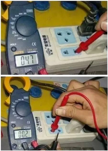
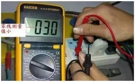
The pointer multimeter should be set to a smaller range (you can select 10V or 100V). Then use the red and black probes connected to V /COM (for measuring the 220V voltage of household sockets) and wrap the black probe lead around your left hand 2-3 times (see the picture). Of course, the more times the better. Be careful: at this time, the metal tip of the black probe must not touch your hand to avoid electric shock. Then you can test; take the red probe and measure the socket or the neutral and live wires. Remember the results of the two measurements; there will definitely be one large and one small voltage. The larger voltage measured is the live wire, and the smaller voltage is the neutral wire. If measuring the ground wire, it will definitely show no voltage or a much lower voltage (depending on whether your ground wire is connected!). Through the measured values of the neutral and live wires, it is clear at a glance.
Source: Internet

 Like it? Click here
 Learn PLC and Electrical Courses for Free, click to read the original text