1. Basic ConceptsPCB materials, also known as Copper Clad Laminate (CCL), are composite materials made up of an insulating substrate and copper foil covering it. The insulating substrate provides mechanical support and electrical insulation, while the copper foil is used to form circuit patterns.As of now, the maximum number of layers for commercially mass-produced PCBs has reached 68 layers, achieved by Nippon Mektron in Japan, used in satellite communication equipment; the highest number of layers in laboratories is 129 layers, with the commercial record being 124 layers at a thickness of 7.6mm;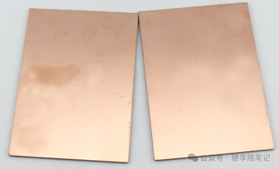 Figure 12. Main Classifications1.Classification by Rigid/Flexible
- Rigid Materials: FR-4, CEM series, aluminum substrates, etc., provide stable support;
- Flexible Materials (FPC): Polyimide (PI), Polyester (PET), etc., can be bent and folded;
Rigid material FR-4 is the most commonly used, and it is also the most familiar due to its large volume and low cost. Among flexible materials, PI is commonly used to make FPC.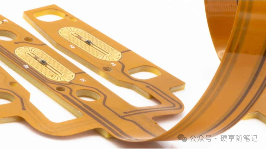 Figure 22.Classification by Material Structure
- Organic Resin Base: FR-4 (glass fiber + epoxy resin), CEM-1 (paper base + epoxy resin);
- Metal Core Base: Aluminum substrates, copper substrates (excellent thermal conductivity);
- Ceramic Base: Aluminum oxide (Al₂O₃), Aluminum nitride (AlN) (high temperature resistance, high insulation);
- High Frequency Specific: Polytetrafluoroethylene (PTFE / Teflon), Rogers series;
3. Detailed Explanation of Mainstream Materials1.FR-4 (Epoxy Glass Fiber Board)Composition:Glass fiber cloth (60%) + Epoxy resin (35%) + Flame retardant (5%)Core Characteristics:
- Dielectric constant (Dk): 4.2~4.8@1MHz;
- Thermal resistance (Tg): 130~180°C;
- High mechanical strength (bending strength about 200MPa);
- Good flame retardancy (UL94 V-0);
- Moderate cost, most widely used (over 70% market share)
- Applications: Computer motherboards, communication devices, industrial control boards, and other conventional electronic products;
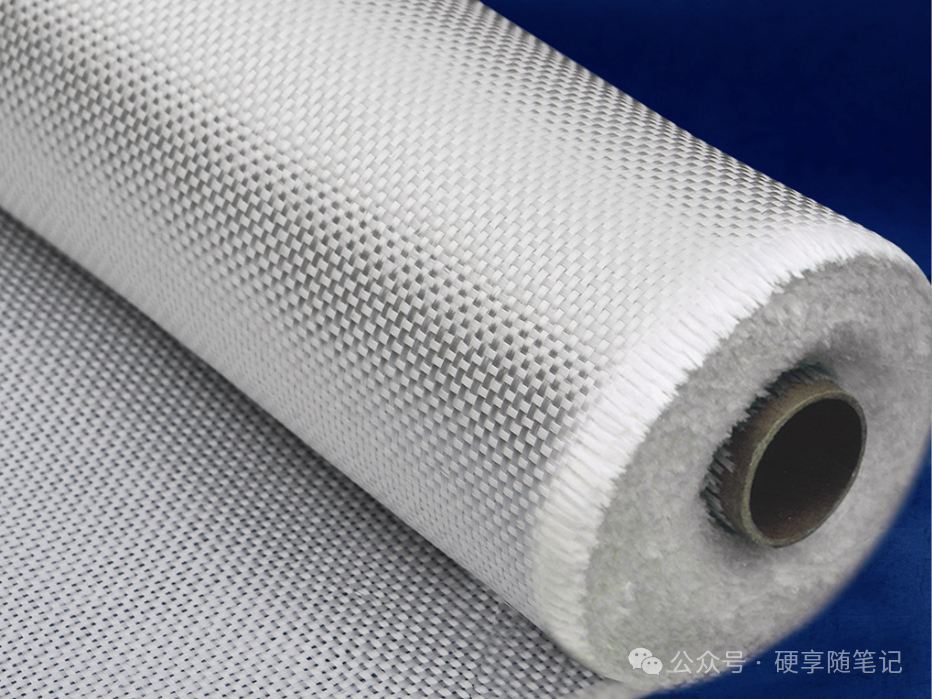 Figure 3The following image shows the characteristics and main application scenarios of different Tg values
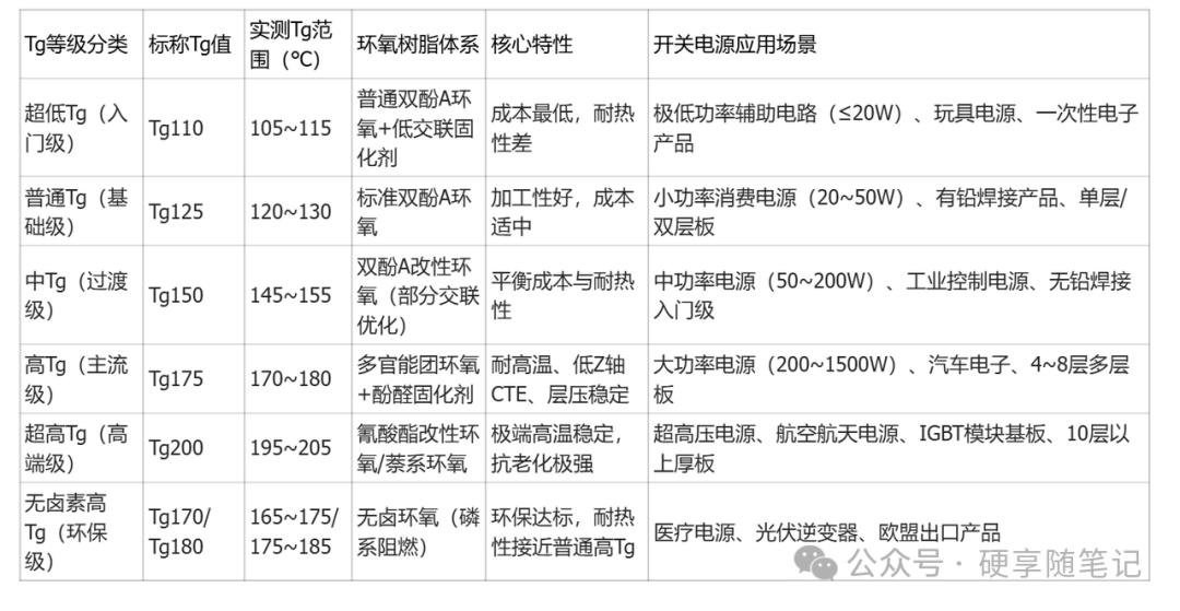 Figure 42.CEM-1/CEM-3
- CEM-1: Paper base + epoxy resin, low cost, Tg about 120°C, suitable for single-sided circuits, mechanical strength lower than FR-4
- CEM-3: Glass fiber mat + epoxy resin, performance between FR-4 and CEM-1, lower cost
- Applications: Household appliances, toys, instruments, and other low-cost products
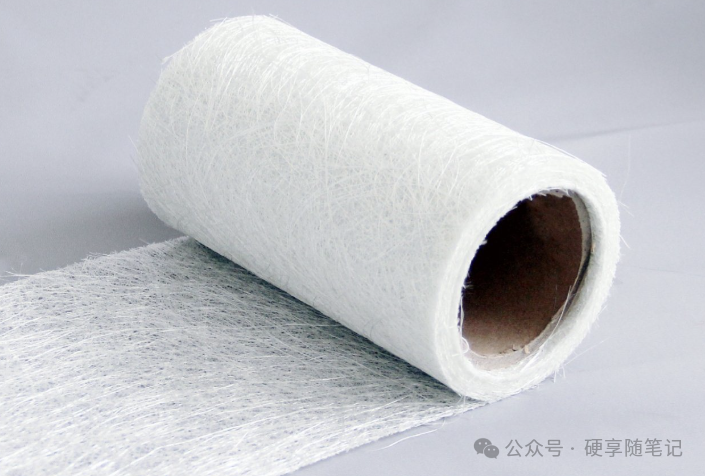 Figure 53.Polytetrafluoroethylene (PTFE)Characteristics:
- Ultra-low dielectric constant (Dk=2.0~2.2) and loss factor (Df<0.0015@10GHz)
- High temperature resistance (Tg>200°C), excellent thermal stability
- Extremely strong chemical stability, almost non-corrosive
- Applications: 5G base station antennas, satellite communications, high-frequency radar, high-end testing instruments
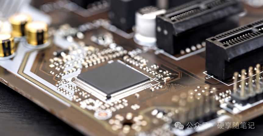 Figure 64.Polyimide (PI)Characteristics:
- Excellent flexibility, can be repeatedly bent
- High temperature resistance (above 260°C)
- Good electrical performance (Dk=3.0~3.5)
- Applications: Wearable devices, foldable phones, flexible display connection circuits
This is the commonly used FPC, often used in places that require bending, and will also have a clearance to increase foldability. In places where increased hardness is needed, the following three reinforcement methods are generally used:Polyimide (PI) Reinforcement: Generally used on the back of the gold finger for plugging, increasing the thickness and mechanical strength of the FPC to fit the connector terminals, with thicknesses ranging from 0.05mm to 0.275mm, which can be made directly during the FPC production process;FR-4 Reinforcement: Generally used for support behind chips or ICs, effectively increasing the mechanical strength of the FPC, improving its resistance to bending and stretching, with conventional thicknesses ranging from 0.1mm to 1.5mm;Metal Reinforcement: Materials include steel sheets, aluminum sheets, copper sheets, etc., with support similar to FR-4, but with additional features such as heat dissipation, grounding, and higher flatness, generally used behind high-end chips or ICs or in some special applications, with conventional thicknesses ranging from 0.1mm to 0.4mm, and other thicknesses can also be customized.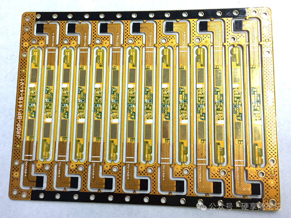 Figure 75.Aluminum Substrate (Al-PCB)Structure:Aluminum alloy base (1mm) + Insulating thermal conductive layer + Copper foil (35μm)Characteristics:
- Low thermal resistance (0.5~3.0°C・in²/W), high heat dissipation efficiency;
- Good mechanical strength, lightweight
- Applications: LED lighting, power modules, automotive electronics, high power density devices, mainly used in applications with high heat generation, commonly found on LED driver boards.
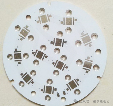 Figure 86.Rogers Series Rogers Corporation is the industry benchmark for high-frequency PCB materials and a global leader in high-performance electronic materials. Its board products are specifically designed for high-frequency, high-speed, and high-power electronic applications, dominating fields such as communications, aerospace, defense, and automotive electronics.
- RO3000® Series: Ceramic-filled PTFE composite materials, providing stable electrical performance and mechanical consistency. Suitable for applications up to 77GHz millimeter waves.
- RO4000® Series: Hydrocarbon ceramic, Dk3.38-3.48, Df0.0027-0.0037, processed similarly to FR-4, many high-frequency applications choose this.
- RO4830 Series: Glass-free thermosetting resin + ultra-low roughness copper foil, specifically for 77GHz automotive corner radar, balancing insertion loss and cost.
The Main Differences Between Rogers High-Frequency Boards and Teflon Rogers high-frequency boards are a type of material specifically designed for high-frequency, high-speed circuits, known for their low dielectric constant and stable electrical performance. Teflon, as a high-performance plastic material, is widely used in various industrial and electronic fields due to its excellent high-temperature and corrosion-resistant properties.
- Cost and Processability: Rogers boards are lower in cost due to their compatibility with standard FR-4 processing technology, making them easy to mass-produce; while Teflon, despite its excellent performance, is more difficult to process and has a higher cost.
- Thermal Performance and Chemical Stability: Teflon performs better in these aspects, especially in applications under extreme conditions.
- Applicable Frequency Range: Although both are suitable for high-frequency applications, Teflon may be more suitable for ultra-high frequency applications due to its extremely low dielectric loss. Of course, cost must also be considered.
Rogers high-frequency boards and Teflon each have their advantages and characteristics, suitable for different application scenarios. Choosing the right material requires consideration of specific circuit requirements, environmental conditions, and cost factors. By understanding these differences in depth, engineers and designers can make more informed decisions to meet specific technical and economic needs. WeChat ID: Hard Sharing NotesWelcome to share and progress togetherRecommended ReadingPCB Production ProcessHow to Differentiate Baud Rate, Bit Rate, Transmission Rate, and Communication Speed?Why do I prefer to use 100Ω for series resistors instead of 22Ω and 33Ω?