RK3588 is Rockchip’s flagship SoC, its PCIe controller, with flexible link splitting capabilities and rich features, has become the core bridge for connecting peripherals such as NVMe, WiFi, AI acceleration cards, etc. This article integrates hardware resource analysis, practical split configuration schemes, key configuration steps, and pitfall points, along with a visual mind map, to help developers quickly implement PCIe related projects.
1. Core Hardware Resources of RK3588 PCIe
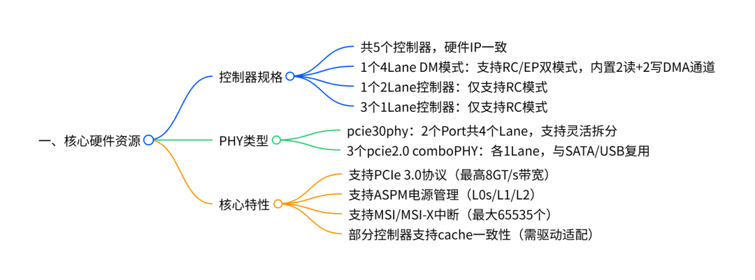
1.1 Controller and PHY Correspondence
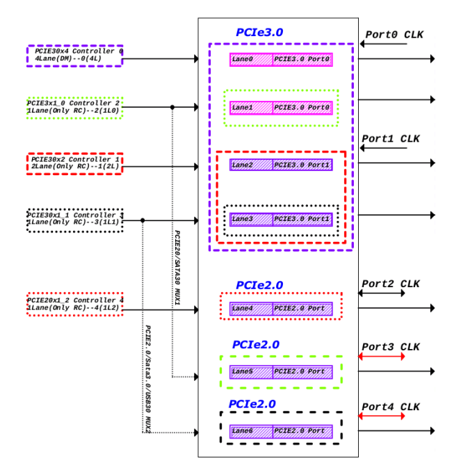
There are fixed rules for the binding of the RK3588 controller and PHY , and the correspondence must be clarified before split configuration:
•pcie3x4 (4Lane): Can only be paired with pcie30phy Port0 (4L/2L/1L mode);
•pcie3x2 (2Lane): Can only be paired with pcie30phy Port1 (2L/1L mode);
•pcie2x1l0/pcie2x1l1: Can bind with pcie30phy (after splitting to 1Lane) or comboPHY;
•pcie2x1l2: Can only bind with comboPHY (e.g., combphy0_ps), and is multiplexed with SATA .
2. Three Core Split Schemes
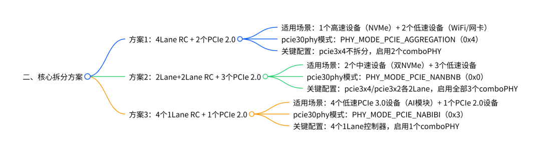
2.1 Scheme 1:4Lane RC + 2 PCIe 2.0 (Basic High-Speed Scheme)
① pcie30phy and High-Speed Controller Configuration
// pcie30phy: 4Lane aggregation mode & pcie30phy { rockchip,pcie30-phymode = <PHY_MODE_PCIE_AGGREGATION>; status = "okay";}; // pcie3x4: 4Lane RC (supports NVMe and other high-speed devices) & pcie3x4 { reset-gpios = <&gpio4 RK_PB6 GPIO_ACTIVE_HIGH>; // PERST# reset signal (must be configured) vpcie3v3-supply = <&vcc3v3_pcie30>; // 3.3V power supply (including external crystal) status = "okay"; // If EP mode is needed, replace compatible: // compatible = "rockchip,rk3588-pcie-ep", "snps,dw-pcie";};② Low-Speed Controller and comboPHY Configuration
// Enable comboPHY (disable SATA multiplexing) & combphy1_ps { status = "okay"; };& combphy2_psu { status = "okay"; };& sata0 { status = "disabled"; }; // Avoid conflict with comboPHY // pcie2x1l0: paired with combphy1_ps (PCIe mode) & pcie2x1l0 { phys = <&combphy1_ps PHY_TYPE_PCIE>; // Specify PCIe mode reset-gpios = <&gpio4 RK_PA5 GPIO_ACTIVE_HIGH>; // Independent reset status = "okay";}; // pcie2x1l1: paired with combphy2_psu & pcie2x1l1 { phys = <&combphy2_psu PHY_TYPE_PCIE>; reset-gpios = <&gpio4 RK_PA2 GPIO_ACTIVE_HIGH>; status = "okay";};③ Power Supply Configuration (vcc3v3_pcie30)
vcc3v3_pcie30: vcc3v3-pcie30 { compatible = "regulator-fixed"; regulator-name = "vcc3v3_pcie30"; regulator-min-microvolt = <3300000>; regulator-max-microvolt = <3300000>; enable-active-high; gpios = <&gpio3 RK_PC3 GPIO_ACTIVE_HIGH>; // PWREN control startup-delay-us = <5000>; // Crystal stabilization time (must be configured to avoid clock anomalies) vin-supply = <&vcc12v_dcin>;};2.2 Scheme 2:2Lane+2Lane RC + 3 PCIe 2.0 (Balanced Scheme)
① Core Split Configuration (pcie30phy + Dual 2Lane Controllers)
// pcie30phy: 2+2 split mode & pcie30phy { rockchip,pcie30-phymode = <PHY_MODE_PCIE_NANBNB>; status = "okay";}; // pcie3x4: reduced to 2Lane RC & pcie3x4 { num-lanes = <2>; // Force 2Lane (must be configured after splitting) reset-gpios = <&gpio4 RK_PB6 GPIO_ACTIVE_HIGH>; vpcie3v3-supply = <&vcc3v3_pcie30>; status = "okay";}; // pcie3x2: 2Lane RC & pcie3x2 { reset-gpios = <&gpio4 RK_PB0 GPIO_ACTIVE_HIGH>; vpcie3v3-supply = <&vcc3v3_pcie30>; status = "okay";};② Configuration of 3 PCIe 2.0 Controllers
// Enable all 3 comboPHYs & combphy0_ps { status = "okay"; };& combphy1_ps { status = "okay"; };& combphy2_psu { status = "okay"; }; // pcie2x1l0~l2 bind to different comboPHYs & pcie2x1l0 { phys = <&combphy1_ps PHY_TYPE_PCIE>; reset-gpios = <&gpio4 RK_PA5 GPIO_ACTIVE_HIGH>; vpcie3v3-supply = <&vcc3v3_pcie30>; status = "okay";}; & pcie2x1l1 { /* Same as pcie2x1l0, reset GPIO changed to RK_PA2 */ };& pcie2x1l2 { /* Same as pcie2x1l0, phys changed to &combphy0_ps, reset GPIO changed to RK_PC1 */ };2.3 Scheme 3:4 1Lane RC + 1 PCIe 2.0 (Multi-Device Scheme)
① Configuration of 4 1Lane Controllers
// pcie30phy: 4×1 split mode & pcie30phy { rockchip,pcie30-phymode = <PHY_MODE_PCIE_NABIBI>; status = "okay";}; // pcie3x4: reduced to 1Lane RC & pcie3x4 { num-lanes = <1>; // Force 1Lane reset-gpios = <&gpio4 RK_PB6 GPIO_ACTIVE_HIGH>; vpcie3v3-supply = <&vcc3v3_pcie30>; status = "okay";}; // pcie3x2: reduced to 1Lane RC & pcie3x2 { num-lanes = <1>; reset-gpios = <&gpio4 RK_PB0 GPIO_ACTIVE_HIGH>; vpcie3v3-supply = <&vcc3v3_pcie30>; status = "okay";}; // pcie2x1l0/l1: bind to pcie30phy (1Lane) & pcie2x1l0 { phys = <&pcie30phy>; // Bind to pcie30phy (not comboPHY) reset-gpios = <&gpio4 RK_PA5 GPIO_ACTIVE_HIGH>; vpcie3v3-supply = <&vcc3v3_pcie30>; status = "okay";}; & pcie2x1l1 { /* Same as pcie2x1l0, reset GPIO changed to RK_PA2 */ };② Configuration of 1 PCIe 2.0 Controller
// Enable 1 comboPHY (disable SATA) & combphy0_ps { status = "okay"; };& sata0 { status = "disabled"; };& pcie2x1l2 { phys = <&combphy0_ps PHY_TYPE_PCIE>; reset-gpios = <&gpio4 RK_PC1 GPIO_ACTIVE_HIGH>; vpcie3v3-supply = <&vcc3v3_pcie30>; status = "okay";};3. Key Configuration and Kernel Options
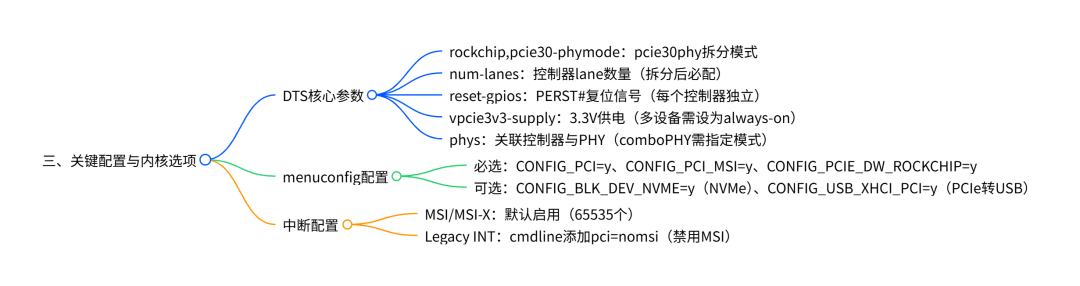
3.1 DTS Parameter Detailed Table
|
Parameter Name |
Configuration Location |
Example Value |
Core Function |
Pitfall Points |
|
rockchip,pcie30-phymode |
pcie30phy node |
PHY_MODE_PCIE_AGGREGATION (0x4) |
Defines the pcie30phy split mode |
Must match the number of lanes of the controller, mismatches are not allowed |
|
num-lanes |
Controller Node |
<1>,<2>,<4> |
Specifies the number of lanes used by the controller |
Must be forcibly configured after splitting, such as in scheme 3 where pcie3x4 is set to <1> |
|
reset-gpios |
Controller Node |
<&gpio4 RK_PB6 GPIO_ACTIVE_HIGH> |
Peripheral reset signal |
Each controller must be configured independently to avoid simultaneous resets of multiple devices |
|
vpcie3v3-supply |
Controller Node |
<&vcc3v3_pcie30> |
Controls the 3.3V power supply |
When multiple controllers share, it must be set to regulator-always-on |
|
phys |
Controller Node |
<&combphy1_ps PHY_TYPE_PCIE> |
Binds the PHY with the controller |
comboPHY must add PHY_TYPE_PCIE, and disable other multiplexing |
|
rockchip,perst-inactive-ms |
Controller Node |
<500> |
Adjusts the reset time |
Increase when peripheral reset is slow (e.g., set WiFi module to 500ms) |
3.2 Required Kernel menuconfig Options
# Basic PCIe supportCONFIG_PCI=yCONFIG_PCI_DOMAINS=yCONFIG_PCI_MSI=y # Enable MSI interruptsCONFIG_PCI_MSI_IRQ_DOMAIN=y# RK PCIe driverCONFIG_PCIE_DW=yCONFIG_PCIE_DW_HOST=yCONFIG_PCIE_DW_ROCKCHIP=y# PHY driverCONFIG_PHY_ROCKCHIP_SNPS_PCIE3=y # pcie30phy driverCONFIG_PHY_ROCKCHIP_NANENG_COMBO_PHY=y # comboPHY driver# Peripheral support (select as needed)CONFIG_BLK_DEV_NVME=y # NVMe SSDCONFIG_USB_XHCI_PCI=y # PCIe to USBCONFIG_SATA_AHCI_PLATFORM=y # PCIe to SATA4. Pitfall Guide and Problem Troubleshooting
4.1 Hardware Pitfalls: 3 Key Points
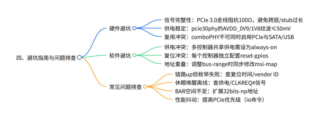
1.Signal Integrity: PCIe 3.0 differential signal routing must control impedance (100Ω±10%), length difference≤5mm, avoid vias across layers and excessive stubs (≤3mm);
2.Power Supply Requirements: pcie30phy ‘s AVDD_0V9 (0.83V~0.99V), AVDD_1V8 (1.62V~1.98V) must be stable, ripple≤50mV, avoid sharing power with other high-current peripherals;
3.Multiplexing Conflicts: comboPHY (e.g., combphy0_ps) supports PCIe/SATA multiplexing, enabling PCIe must disable SATA (&sata0 { status = “disabled”; }), and vice versa.
4.2 Software Pitfalls: 4 Common Scenarios
|
Scenario |
Common Errors |
Correct Approach |
|
Power Supply for Multiple Controllers |
Individually configuring a specific controller vpcie3v3-supply |
Set shared power supply to regulator-always-on, example:regulator-always-on; |
|
Address Overlap After Splitting |
Not adjusting bus-range causing address conflicts |
Allocate independent bus addresses for each controller, synchronize modifications to msi-map:bus-range = <0x30 0x60>; msi-map = <0x3000 &its 0x3000 0x3000>; |
|
Insufficient Peripheral Reset |
Insufficient reset time leading to enumeration failure |
Increase rockchip,perst-inactive-ms:rockchip,perst-inactive-ms = <500>; |
|
Cache Consistency Issues |
Using memcpy to access BAR space causing exceptions |
Use IO dedicated API: memset_io, memcpy_toio, use loop assignment in user space |
4.3 Common Problem Troubleshooting Quick Reference Table
|
Problem Phenomenon |
Possible Causes |
Solutions |
|
Link up (LTSSM=0x30011) but unable to enumerate devices |
1. Peripheral vendor ID is 0xffffffff/0x0; 2. Insufficient reset time |
1. Add vendor ID print in drivers/pci/probe.c;2. Set rockchip,perst-inactive-ms=500 |
|
Some controllers unresponsive after splitting |
1. Controller and PHY binding error; 2. No power supply provided for pcie30phy unused Port |
1. Confirm pcie3x4 is bound to Port0, pcie3x2 is bound to Port1; 2. Even if only one Port is used, the other Port still needs power |
|
Device offline after sleep wake-up |
1. 3.3V power supply turned off during sleep; 2. CLKREQ# signal not configured |
1. Set power supply to regulator-always-on; 2. Add supports-clkreq property to the controller node |
|
BAR space allocation failure (log contains “no space for”) |
1. Insufficient 32bits-np address; 2. Switch invalid port occupying resources |
1. Expand address (refer to document 7.18 section to modify ranges);2. Filter invalid ports (probe.c blacklist) |
|
Performance jitter (e.g., AI card frame rate fluctuations) |
PCIe controller memory priority is low |
Execute command to increase priority:io -4 0xfdf3a008 0x404 (common for all controllers) |
Through the hardware resource analysis, split scheme practice, configuration points, and pitfall guide in this article, developers can quickly complete the adaptation and debugging of RK3588 PCIe . If further simplification of configuration is needed, a project template can be created based on the “split scheme + parameter table” organized in this article to improve development efficiency.