When starting to learn PCB design, it is often emphasized by experts to separate strong electricity and weak electricity. So what exactly are these two types of “electricity” and how can they be distinguished?
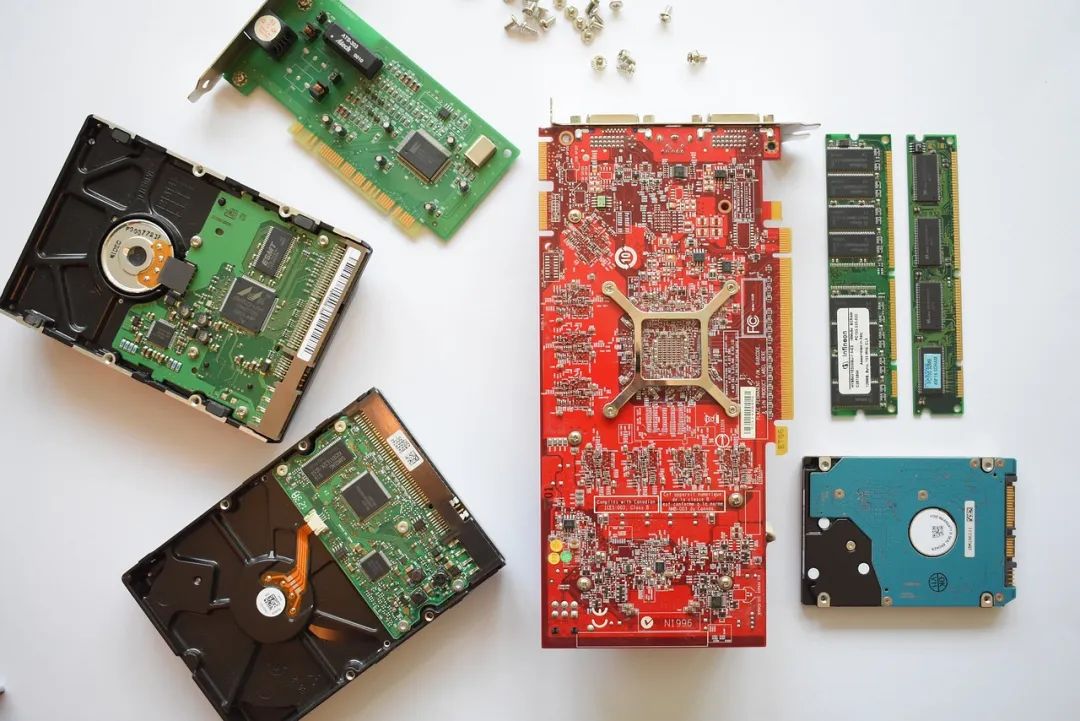
1. What Are Strong and Weak Electricity?
Strong Electricity: Definition: Refers to alternating current or direct current greater than 2V (usually greater than or equal to 24V or 220V), which can cause harm. Voltage Range: For example, household light bulbs and sockets, with voltages ranging from 110 to 220V. Weak Electricity: Definition: Generally refers to digital circuits, analog circuits, and control circuits, which have lower voltages and higher safety. Voltage Range: Direct current voltage is usually within 32V, such as signal inputs from telephones, computers, and televisions in household appliances.
2. Characteristics of Strong and Weak Electricity
Strong Electricity: Characteristics: High voltage, low frequency (usually 50Hz), large current. Application: Used to drive high-power electrical devices such as lighting fixtures, refrigerators, and televisions. Weak Electricity: Characteristics: Low voltage, high frequency (measured in kHz or MHz). Application: Used for signal transmission, such as telephone lines, network lines, and audio-video lines.
3. How to Isolate Strong and Weak Electricity?
Pin Distance: Increase the distance between strong and weak electricity pins to physically isolate them. Shielding: Use metal shields to separate strong and weak electricity circuits to avoid electromagnetic interference. Isolation Gaps: Cut the PCB to isolate strong and weak electricity circuits. Magnetic Isolators and Opto-Isolators: Use magnetic fields or optoelectronic components to separate strong and weak electricity circuits.
This article is an original piece from Fan Yi Enterprise Training. Please indicate the source when reprinting!
Submissions/Recruitment/Advertising/Course Cooperation/Resource Exchange; Please add WeChat: 13237418207