LiDAR is crucial for autonomous driving, as it measures distances by emitting laser beams and generates high-precision point cloud data, helping vehicles determine the spatial position and geometric shape of surrounding objects. This article mainly introduces the principles and classifications of LiDAR.Working Principle
1. Introduction
The full name of LiDAR is Light Detection and Ranging, also known as optical radar.
The principle of LiDAR: It detects objects by emitting, reflecting, and receiving harmless infrared light beams. It can detect the distance between specific objects and the vehicle, whether during the day or at night. It can even distinguish lane markings and road surfaces due to differences in reflectivity. However, objects that are obstructed cannot be detected.
2. Working Principle
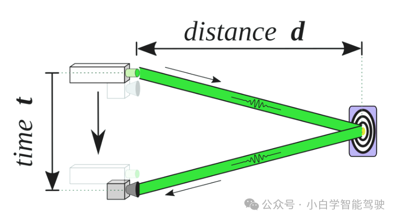
The working principle of automotive LiDAR is the Time of Flight (ToF) detection method, which measures distance by calculating the time it takes for light to travel a certain distance in a medium. It is mainly applied in optical ToF scenarios, and its principle is relatively straightforward. As shown in the figure, a light source emits a beam of light and records the emission time. This beam reflects off a target and is captured by a receiver, which records the reception time. The difference between these two time points, denoted as t, can be used to calculate the distance d = speed of light c * t /2
3. Wavelength Characteristics
The mainstream wavelengths of LiDAR currently are 905nm and 1550nm, with the following specific comparisons:

LiDAR Structure
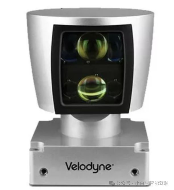
System Composition
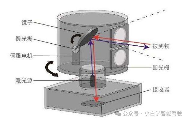
A typical LiDAR system consists of a laser emission source, a receiver, a servo motor, a mirror, and an optical rotary encoder (also known as a circular grating).
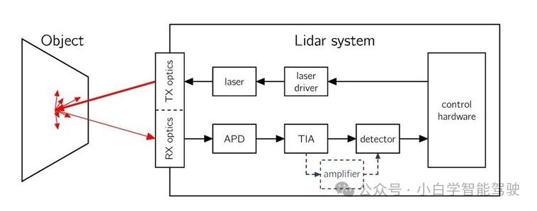
Key Components
The key components of LiDAR include control hardware DSP (Digital Signal Processor), laser driver, laser emission LED, emission optical lens, receiving optical lens, APD (Avalanche Photodiode), TIA (Transimpedance Amplifier), and detector, arranged according to the signal processing chain. Except for the emission and receiving optical lenses, all are electronic components. With the rapid evolution of semiconductor technology, performance has gradually improved while costs have rapidly decreased. However, optical components and rotating machinery account for a significant portion of LiDAR’s total cost.
LiDAR ClassificationLiDAR can be mainly classified intomechanical, hybrid solid-state, andpure solid-state based on the different scanning methods of its beams.
1. Mechanical Scanning LiDAR
Mechanical LiDAR is the earliest developed technology, and its working principle is to drive the entire laser emission and reception module to rotate 360° through a motor, achieving panoramic scanning. Its core advantages arewide field of view (360° coverage), mature technology, and the ability to achieve extremely long-range measurements and high resolution through multi-beam layouts. However, its fatal drawbacks arelarge size, high cost, and poor reliability and short lifespan due to the presence of high-speed rotating mechanical parts, making it difficult to meet the stringent pre-installation mass production requirements of the automotive industry. Therefore, it is currently mainly used in specific fields such as autonomous driving research, high-precision map collection, and robotics.
Mechanical Structure Schematic
2. Hybrid Solid-State LiDAR
Hybrid solid-state technology is currently the mainstream in the automotive pre-installation market. It retains some microscopic moving parts but no longer rotates as a whole, achieving the best balance between reliability, performance, and cost. It mainly includes two technical paths:
Mirror/Prism Scheme: This scheme fixes the laser emitter and receiver and uses a motor to drive a small mirror (such as a multi-faceted mirror or wedge prism) to rotate or vibrate to reflect the laser for scanning. Itsreliability is significantly higher than that of mechanical systems, making it easier to pass automotive certification, while also providing good ranging and resolution performance, and is easy to mass-produce. The main drawback is thatthe field of view is usually limited to about 120° forward, and it still has not completely eliminated moving parts.
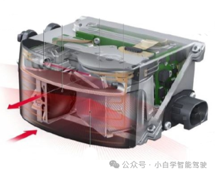 Mirror Rotation Schematic
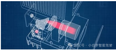 Prism Schematic
MEMS (Micro-Electro-Mechanical Systems) Scheme: This scheme uses electromagnetically driven micro-mirrors to reflect laser beams. Its greatest advantages aresmall size, low cost, fast scanning speed, and high precision, thanks to chip technology, making it very suitable for mass production. However, itsfield of view is relatively small, and there are certain limitations in ranging capability and adaptability to environmental vibrations.
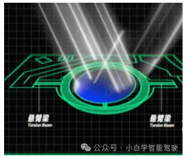
Micro-Mirror Structure Schematic
3. Pure Solid-State LiDAR
Pure solid-state LiDAR completely eliminates all mechanical moving parts and is the ultimate direction for future technological development, mainly including Flash and OPA.
Flash Scheme: It works by emitting a plane array of laser beams to the entire field of view in an instant, similar to a camera flash, and captures all distance information at once with a highly sensitive receiver array. Its greatest advantages areextremely high reliability, very fast scanning speed (no scanning motion), and ease of chip-based mass production. However, to ensure safety for human eyes, its single-point power is relatively low, resulting inshort effective detection distance and relatively sparse point cloud resolution. This makes it very suitable forlow-speed autonomous driving, blind-spot radar, and robot obstacle avoidance scenarios.
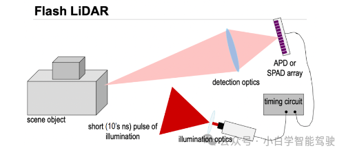
Flash LiDAR Principle
OPA (Optical Phased Array) Scheme: This is a cutting-edge technology that achieves inertial-free electronic control scanning of beams through precise control of the phase of each unit in the laser emission array, using interference principles. It is hailed as the “ultimate solution,” possessingfast scanning speed, high precision, fully solid-state, and small size potential. However, this technologyis still very immature, facing technical bottlenecks such as sidelobe interference and complex manufacturing processes that need to be overcome, and has not yet achieved large-scale commercial application.
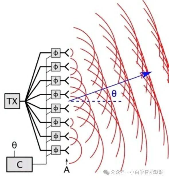
OPA Optical Phased Working Principle
LiDAR can be mainly divided into main radar and blind-spot radar based on functionality.
Main Radar
-
Function Positioning: As thecore perception sensor of the system, it provides long-distance, high-precision 3D environmental information for the main area in front of the vehicle.
-
Installation Position: Typically installed on theroof of the vehicle or above thefront windshield to achieve the best forward visibility.
-
Core Tasks:
-
Long-Distance Target Recognition: Identifying vehicles, pedestrians, and other obstacles from 120-200 meters or even further in advance.
-
Safety Assurance in High-Speed Scenarios: Providing sufficient decision-making and planning time for the autonomous driving system.
-
Lane Line and Drivable Area Judgment: Assisting in precise positioning and path planning.
-
Performance Requirements:
-
Long Detection Distance (usually > 150m @ 10% reflectivity)
-
High Resolution (able to clearly distinguish small objects at a distance)
-
Medium to Long Field of View (usually around 120° horizontally, to meet high-speed cruising needs)
-
Typical Technical Solutions:Hybrid Solid-State Radar (Mirror/MEMS) is currently the mainstream choice for main radar due to its balance of performance, reliability, and cost.
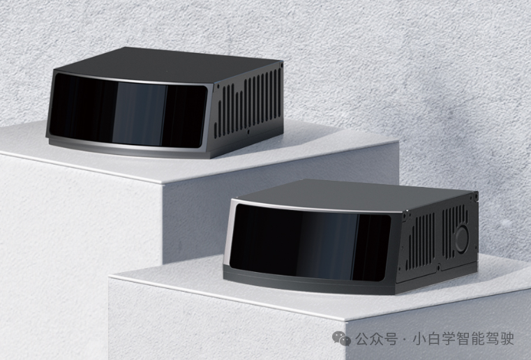
Example: Volkswagen Sagitar M1P
2. Blind-Spot Radar
-
Function Positioning: As asupplement to the main radar and cameras, it is responsible for covering the perception blind spots in the vehicle’s close vicinity, providing dense point cloud information.
-
Installation Position: Typically installed on theside of the vehicle (e.g., B-pillar), both sides of the front, or the rear.
-
Core Tasks:
-
Blind Spot Monitoring: Detecting areas on the sides and corners that the main radar and cameras cannot cover.
-
Close-Range Cut-In Scenarios: Quickly identifying vehicles that suddenly cut in from the side.
-
Unprotected Left Turns/Intersections: Identifying pedestrians and vehicles crossing laterally.
-
Low-Speed Parking and Narrow Passage Navigation: Accurately perceiving surrounding obstacles to ensure safety.
-
Performance Requirements:
-
Ultra-Wide Field of View (usually > 120° horizontally, even reaching 180°)
-
Short to Medium Range Detection (usually < 50m, but with high requirements for near-field point cloud density)
-
Compact Size and Low Cost, facilitating deployment in multiple locations on the vehicle.
-
Typical Technical Solutions:Pure Solid-State Flash LiDAR andShort-Range MEMS LiDAR are ideal choices for blind-spot radar due to their no moving parts, compact size, and ability to meet near-field wide-angle requirements.
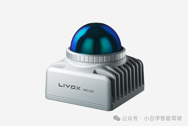 Example: Livox mid360
The next article will introduce LiDAR performance indicators and how to select and evaluate them.
References:
https://zhuanlan.zhihu.com/p/602055107
https://community.infineon.com/t5/%E5%8D%9A%E5%AE%A2/%E7%A7%91%E6%99%AE-%E6%BF%80%E5%85%89%E9%9B%B7%E8%BE%BELIDAR%E5%B7%A5%E4%BD%9C%E5%8E%9F%E7%90%86/ba-p/549028#.
https://www.lumimetric.com/cn/new/TOF-time-of-flight-definition-and-principle.html
https://getiot.tech/lidar/lidar-technology-types/
https://www.liangdao.com/cn/index.php/News/show?id=119
初心 | Sharing and exchanging experiences and knowledge in the field of intelligent driving.Statement |Some images and texts are sourced from the internet. If there is any infringement, please contact for modification or deletion; the article only represents personal views. If there are any inappropriate points, please also contact for modification or deletion.