(Written by Bai Yujie, Senior Application Engineer)
Abstract
Today, the automotive industry has an unprecedented demand for advanced display screens, requiring solutions that can achieve larger sizes, higher brightness, curved designs, higher resolutions, and greater contrast ratios. Meanwhile, various new types of in-vehicle display screens are increasingly favored. Currently, TFT LCD is the mainstream choice for automotive flat panel display technology. OLED and micro-LED displays, with their excellent display effects, low energy consumption, high flexibility, and ultra-thin characteristics, are gradually gaining the attention of automotive manufacturers. This article compares these different display technologies and discusses the 2T1C pixel driver suitable for LCD displays, as well as the 7T1C/2C pixel drivers suitable for OLED and micro-LED displays.
Introduction
This article is the first part of a two-part series on TFT LCD, OLED, and micro-LED displays in automotive applications. It compares the characteristics of TFT LCD, OLED, and micro-LED displays, as well as the technologies of different pixel drivers. Additionally, it discusses the power supply technology for TFT technology and automotive displays.
The first part of this series focuses on the basic principles of automotive displays, including development trends, challenges, and display structures. To aid in understanding the power supply technology for automotive displays, the article also briefly introduces pixel drivers.
The second part of this series will cover the power supply technology for automotive displays. The article discusses different display technologies, including edge-lit and direct-lit backlighting. It also briefly explains the local dimming technology of mini-LED displays.
Trends in Automotive Digital Cockpits
In recent years, the automotive sector has rapidly developed in areas such as the Internet of Vehicles, electrification, autonomous driving, and shared mobility. To provide users with a better experience, the design of the cockpit has also undergone a complete transformation. There is an increasing demand for larger, curved designs, higher resolution, and greater contrast ratio displays, as well as new types of in-vehicle displays. According to the IHS Markit automotive display market tracking report, the shipment volume of automotive display panels was 161.5 million units in 2018, and it is expected to exceed 200 million units by 2025.
To enhance the cockpit experience, modern vehicles are equipped with various types of displays: dashboards, central information displays (CID), head-up displays (HUD), passenger displays, smart electronic rearview mirror displays, side mirror displays, and rear entertainment displays. The dashboard provides key information such as speed and fuel gauge status to the driver. The HUD projects key information onto the windshield. Rear seat entertainment displays and passenger displays are part of the infotainment system, allowing passengers to watch movies or engage in other entertainment activities. The digital camera monitoring system (CMS) replaces external rearview mirrors with two to three cameras. Meanwhile, side mirror displays and electronic rearview mirror displays enhance the driver’s visual perception of the surrounding environment.
According to the IHS Markit automotive display market tracking report, in 2018, 10-inch panels accounted for 10% of automotive display panel shipments, and this proportion is expected to grow to 18.4% by 2025. In recent years, 12.3-inch and larger display panels have gradually become the mainstream size for dashboard displays.
Since the Tesla Model 3 was equipped with a 15-inch touchscreen in 2017, automotive display panels have been evolving towards larger sizes, higher resolutions, and greater contrast ratios, with increasing freedom in design forms. In 2019, the Li Auto ONE adopted a full-width cockpit display, consisting of two screens measuring 12.3 inches and 16.2 inches, respectively. In 2023, the BMW 3 Series was equipped with a 14.9-inch curved touchscreen that utilizes local dimming technology, extending from the driver’s side to the center console. The VISION EQXX concept car features a 47.5-inch full-width screen with local dimming technology. The trends in automotive displays are summarized in Figure 1.
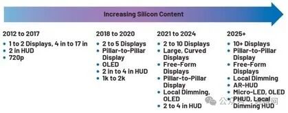
Figure 1. Trends in Cockpit Displays
The full windshield HUD on the BMW concept car Neue Klasse is expected to enter mass production in 2025. This innovative HUD technology can project information across the entire front windshield, allowing all passengers to easily view it. The lower edge of the windshield has higher light intensity and contrast, displaying relevant information to both the driver and passengers. Additionally, there is a free-form central display.
Display Panel Architecture
Figures 2, 3, and 4 represent three different technologies: TFT LCD, OLED, and micro-LED, which are driving innovations in visual displays.
TFT LCD uses liquid crystals sandwiched between two layers of glass substrates to display images. The lower substrate embeds the TFT, while the upper substrate serves as a color filter. By controlling the current flowing through the transistors, the electric field can be altered, which in turn affects the arrangement of liquid crystal molecules, modulating the rotation state of light passing through the liquid crystal layer. By illuminating the filter with different proportions of red, green, and blue light, pixels of various colors can be formed.
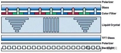
Figure 2. Structure of TFT LCD Display
In contrast, OLED displays have self-emissive capabilities, eliminating the need for backlighting. The basic structure of OLED includes an indium tin oxide (ITO) glass substrate and an organic light-emitting layer on top. The organic light-emitting layer is sandwiched between two low work function metal electrodes: the upper cathode and the lower anode.
When an external voltage is applied across the cathode and anode, the electron transport layer (ETL) and hole transport layer (HTL) inject electrons and holes into the organic light-emitting layer, with the quantity and speed of injection being controllable. This process causes the OLED to emit light. Different chemical materials used in OLED can produce red, green, and blue light. Therefore, OLED displays are thinner, more energy-efficient, and have superior color reproduction and contrast.
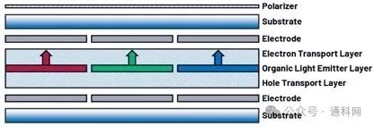
Figure 3. Structure of OLED Display
Micro-LED displays consist of micro-LED arrays forming each pixel, representing a new advancement in display technology. Typically, micro-LED chip sizes are less than 50 µm, making them nearly invisible to the human eye. Thanks to their small size and advanced assembly technology, red, green, and blue light sources can be integrated into a single pixel point, allowing micro-LED displays to operate without filters and liquid crystals.
Each micro-LED in a pixel can emit light independently, resulting in higher brightness, deeper blacks, and excellent energy efficiency. These technologies represent significant advancements in display innovation, with each technology having unique advantages in structure and performance. Micro-LED displays are suitable for a wide range of applications, from smartphones and TVs to augmented reality, wearables, and automotive displays.
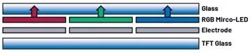
Figure 4. Structure of Micro-LED Display
TFT LCD technology is relatively mature and has significant cost advantages, making it the dominant flat panel display technology in the automotive industry. However, OLED and micro-LED displays are also attracting increasing attention from automotive manufacturers.
OLED displays offer excellent display effects, low energy consumption, high flexibility, and ultra-thin characteristics. Micro-LED displays are emerging as the next generation of display technology, supporting curved display designs, enhanced brightness and contrast, and providing greater flexibility for cockpit screen designs.
However, OLED displays have issues with image retention, where pixel performance degrades after displaying static images for extended periods, and their lifespan is shorter than that of LCDs. Meanwhile, the mass production commercialization of micro-LED displays faces challenges, with high costs remaining a barrier.
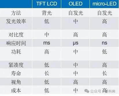
Table 1 summarizes the differences between TFT LCD, OLED, and micro-LED displays.
Table 1. Comparison of LCD, OLED, and Micro-LED Displays
Existing TFT LCD displays can be upgraded using mini-LED (sub-millimeter light-emitting diodes) backlight sources and local dimming technology. Mini-LED is a miniaturized version of conventional LEDs and serves as a technological bridge to micro-LED. LEDs smaller than 200 micrometers are classified as mini-LEDs, while those smaller than 100 micrometers are classified as micro-LEDs.
Although mini-LED is primarily used as a backlight source for LCD displays, it can reduce the thickness of LCD displays, enhance contrast performance, and help achieve cost-effective solutions.
Pixel Drivers
By mixing the three primary colors (red, green, blue), various colors can be synthesized. The mixed primary colors form a pixel, as shown in Figure 5. Each pixel consists of three sub-pixels, which are managed uniformly and combined into one pixel.
Due to differences in display technology and manufacturing processes, TFT LCD, micro-LED, and OLED displays use different methods to drive these sub-pixels. For example, the Tesla Model 3 features a 15.4-inch TFT LCD display with a resolution of 1920 x 1200 pixels, resulting in a total of 6.91 million sub-pixels.
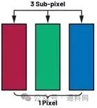
Figure 5. Pixel
The equivalent circuit of sub-pixels in a TFT LCD display (controlling the electric field on the liquid crystal) is shown in Figure 6. It consists of 1T2C (one transistor, one liquid crystal capacitor, and one storage capacitor). The gate driver provides positive and negative voltages. The positive voltage is referred to as the gate high-level voltage (VGH), which turns on the TFT. The negative voltage is referred to as the gate low-level voltage (VGL), which turns off the TFT. Image information is transmitted to the source driver, which charges the liquid crystal capacitor (CLC). The storage capacitor (CST) acts as a buffer to prevent leakage current from the CLC. For more discussions on pixel drivers in TFT LCD displays, please refer to “New Driving Structure to Increase Pixel Charging Ratio for UHD TFT-LCDs With High Frame Rate”.
Image retention or flickering in TFT LCDs is caused by the parasitic capacitance (CGD) between the gate node and the drain node of the TFT. When the content of the image changes, and the TFT switches from the on state to the off state, the capacitive voltage divider between CGD and CLC||CST causes the voltage of CLC to drop. To improve the consistency of panel performance, we introduce a common backplane voltage (VCOM) during pixel transition time and adjust it to the midpoint of the pixel voltage.
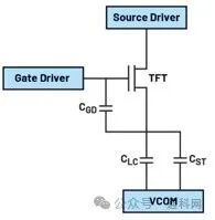
Figure 6. Conventional Pixel Driver
The topologies of commonly used pixel drivers in micro-LED and OLED displays are similar but more complex than those in TFT LCD displays. This is due to the manufacturing processes of TFT circuits and the need to integrate LEDs on glass or polyimide substrates. This allows each LED in a pixel to be driven individually, enabling independent control of their brightness.
As shown in Figure 7, the simple pixel driver 2T1C described in “Driving Technologies for OLED Display” includes two transistors and one storage capacitor. In this pixel driver, the analog signal emitted by the LED is sent to TFT M1. Subsequently, the threshold voltage (VGS) is stored in the capacitor (CST) to drive TFT M2 in the saturation region, as shown in Figure 8. Due to the driving of TFT M2, the positive voltage (VDD) and cathode voltage (VSS) maintain a constant current through the LED. This saturation operation driving method of the 2T1C pixel driver has the advantage of extending the LED lifespan compared to the linear region operation of driving the TFT.
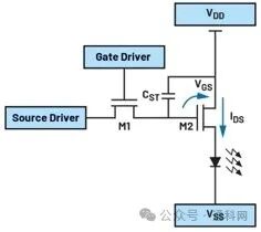
Figure 7. 2T1C Pixel Driver for OLED or Micro-LED
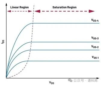
Figure 8. MOS Transistor Output Characteristics
However, the 2T1C pixel driver also has some drawbacks, including Mura issues and threshold voltage shifts under electrical bias. The Mura issue refers to uneven brightness on the display, primarily caused by variations in the manufacturing process, such as the density of the TFT layer and the uniformity of the forward voltage of the LED relative to the threshold voltage, which can lead to image quality problems. Although excellent manufacturing processes cannot overcome the challenge of threshold voltage drift, the industry has proposed pixel circuits using voltage feedback methods and threshold voltage offset overcompensation methods to improve image quality.
The 7T1C method proposed in “Image Quality Enhancement in Variable-Refresh-Rate AMOLED Displays Using a Variable Initial Voltage Compensation Scheme” has three operational stages: initialization, compensation, and emission, as shown in Figure 10. TFT M4 is used to drive the diode connected to TFT M3. During compensation, the voltage from the source driver stored in CST maintains the LED emission. TFT M1, M6, and M7 are used to prevent the LED from lighting up. Additionally, a 7T2C pixel circuit is proposed in “A Highly Uniform Luminance and Low-Flicker Pixel Circuit and Its Driving Methods for Variable Frame Rate AMOLED Displays”.
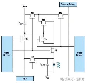
Figure 9. Schematic of 7T1C Pixel Driver
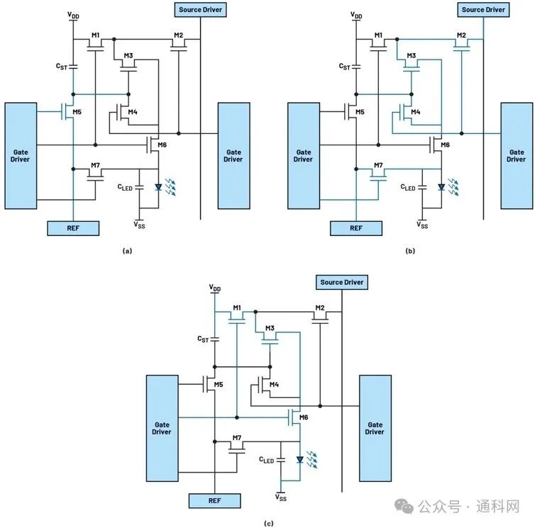
Figure 10. Driving Sequence of 7T1C Compensation Pixel: (a) Initialization, (b) Compensation, and (c) Emission.
Currently, display backplane technology has evolved from hydrogenated amorphous silicon (a-Si:H) TFT to low-temperature polycrystalline silicon (LTPS) TFT, while low-temperature polycrystalline silicon with oxide (LTPO) TFT is expected to become the next generation of backplane technology for consumer electronics. The carrier mobility of a-Si:H TFT is relatively low (1 cm2/Vs), resulting in larger backplane sizes and higher power consumption. LTPS TFT has excellent carrier mobility (>50 cm2/Vs), making it suitable for OLED displays. LTPS TFT typically has higher off-state current. However, LTPO TFT has lower off-state current. Therefore, the industry is considering hybrid pixel schemes that combine the advantages of both LTPS and LTPO TFT for OLED/micro-LED display backplanes.
Conclusion
As consumer expectations for visibility, safety, and user experience continue to rise, the importance of in-vehicle display screens in enhancing the cockpit experience is becoming increasingly prominent. To achieve high-quality, high-resolution, high-contrast, free-form, large-size, and cost-effective automotive display solutions, several significant challenges still need to be overcome.
This article discusses the characteristics of TFT-LCD, OLED, and micro-LED displays. To achieve better display performance, the pixel driving of OLED and micro-LED displays has become more complex compared to TFT-LCD displays. Meanwhile, the mass production commercialization of OLED and micro-LED displays faces challenges, with prices remaining high. Mini-LED LCD displays with local dimming technology serve as a bridge to micro-LED and OLED displays.
The second part of this series will focus on the power supply technology for automotive displays, including backlight drivers, TFT bias PMICs, and local dimming functions.
References
1 You Xiang Stacy Wu. “Automotive Display Market Outlook”. 2019 26th International Workshop on Active-Matrix Flatpanel Displays and Devices (AM-FPD), IEEE, September 2019.
2 Robert Prange. “Trends in Automotive Display Glass Processing”. Glastory, December 2024.
3 “What Are Micro LED, Mini LED, and Micro OLED? Different Emerging Display Technologies Explained”. LEDinside, August 2021.
4 Chih-Lung Lin, Jui-Hung Chang, Fu-Hsing Chen, Po-Cheng Lai, Yi-Chien Chen, and Cheng-Han Ke. “New Driving Structure to Increase Pixel Charging Ratio for UHD TFT-LCDs With High Frame Rate”. IEEE Access, Vol. 10, August 2022.
5 Yojiro Matsueda. “Driving Technologies for OLED Display”. Handbook of Organic Light-Emitting Diodes, Springer, 2022.
6 Li Jin Kim, Sujin Jung, Hee Jun Kim, Bong Hwan Kim, Kyung Joon Kwon, Yong Min Ha, and Hyun Jae Kim. “Image Quality Enhancement in Variable-Refresh-Rate AMOLED Displays Using a Variable Initial Voltage Compensation Scheme”. Scientific Reports, Vol. 12, April 2022.
7 Younsik KIM, Kyunghoon Chung, Jaemyung Lim, and Oh-Kyong Kwon. “A Highly Uniform Luminance and Low-Flicker Pixel Circuit and Its Driving Methods for Variable Frame Rate AMOLED Displays”. IEEE Access, Vol. 11, 2023.
Author Biography
Yujie Bai is a Senior Application Engineer at ADI, responsible for supporting and applying automotive power products. Yujie joined Maxim Integrated (now part of ADI) in 2020 and holds a Master’s degree in Electrical Engineering from the University of Miami, Ohio.