“Assembly Language”, 3rd Edition by Wang Shuang
Chapter 13 int Instruction (Page 262)
Experiment 13 Writing and Applying Interrupt Routines
————————————
Note: This is the code example and analysis for Experiment 13Question 1.
———————————–
(1) Write and install the int 7cH interrupt routine, which displays a null-terminated string. The interrupt routine is installed at 0:200.
Parameters: (dh)=line number, (dl)=column number, (cl)=color, ds:si points to the start address of the string.
Requirement: After successfully installing the above interrupt routine, step through the following program, paying particular attention to the state of CS, IP, and the stack before and after executing the int and iret instructions.
Test Program: Display “welcome to masm!” in green at line 10, column 10.
assume cs:codedata segment db "welcome to masm!",0data endscode segment start: mov dh, 10 mov dl, 10 mov cl, 2 mov ax, data mov ds, ax mov si, 0 int 7cH mov ax, 4c00H int 21Hcode endsend start
==================
Example code for the 7cH interrupt routine and installation program is as follows:
;"Assembly Language", 3rd Edition by Wang Shuang; Chapter 13 int Instruction (Page 251); Experiment 13 Writing and Applying Interrupt Routines;(1) Write and install the int 7cH interrupt routine, which displays a null-terminated string
assume cs:codecode segment           ;Copy the machine code of the 7cH interrupt routine to 0:200H
    start: mov ax, code           mov ds, ax           mov si, offset int7c_begin           mov ax, 0           mov es, ax           mov di, 200H           mov cx, offset int7c_end - offset int7c_begin           cld           rep movsb           ;Set the interrupt vector for the 7cH interrupt           mov ax, 0           mov es, ax           mov word ptr es:[7cH*4], 200H           mov word ptr es:[7cH*4+2], 0           ;Exit after installation           mov ax, 4c00H           int 21H
                 ;7cH interrupt handler, displays a null-terminated string at the specified line and column                 ;Input parameters: (dh)=line number,(dl)=column number,(cl)=attribute,                 ;      ds:si points to the start address of the string    int7c_begin: push ax  ;Save the used registers on the stack                 push cx                 push es                 push di                 push si                 mov ax, 0B800H  ;Video memory segment address                 mov es, ax                 mov ax, 160                 mul dh                 mov di, ax                 mov ax, 2                 mul dl                 add di, ax      ;Starting position for screen display                 mov al, cl       show_str: mov cl, [si]                  mov ch, 0                 jcxz int7c_ret                 mov es:[di], cl                 inc di                 mov es:[di], al                 inc di                 inc si                 jmp short show_str      int7c_ret: pop si                 pop di                 pop es                 pop cx                 pop ax                 iret      int7c_end: nop           code endsend start
The debugging trace process is as follows:
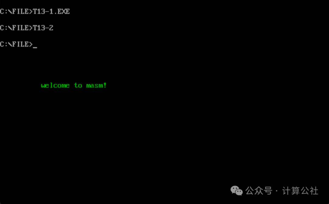
1. After installing the 7cH interrupt routine, run the test program, and the screen displays the relevant text, indicating that the program is functioning normally, as shown in the figure below.
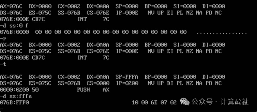
2. Step through the test program as required, before executing int 7cH, (CS)=076E, (IP)=000E, and the stack data is all 0, as shown in the figure below.

3. After executing int 7cH, (CS)=0000, (IP)=0200, and the stack data is 10 00 6E 07 02 72, as shown in the figure below. These correspond to the values of the IP, CS, and FLAG registers, which are pushed onto the stack during the int interrupt.
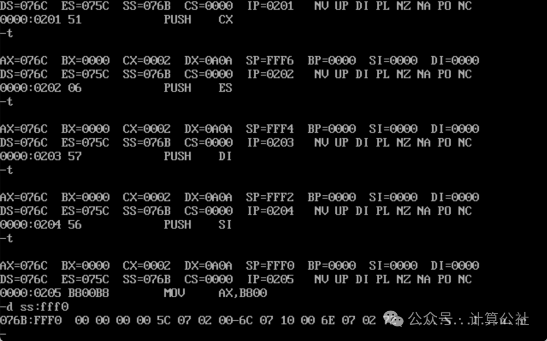
4. Inside the 7cH interrupt routine, after pushing ax, cx, es, di, and si onto the stack, the stack data is shown in the figure below.
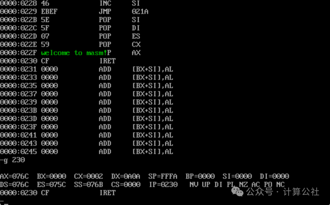
5. Using the g command to jump to the iret location, you can see that the screen has already displayed the content to be output, as shown in the figure below.
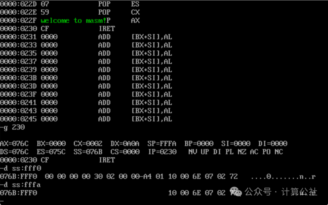
6. Before executing iret, check the relevant registers and stack again, (CS)=0000, (IP)=0230, and the stack (SS:SP) data is still 10 00 6E 07 02 72, as shown in the figure below.
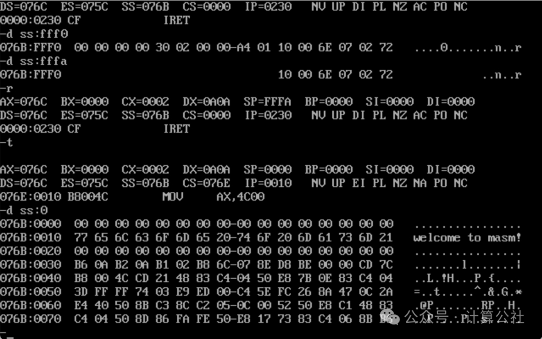
7. After executing iret, returning from the interrupt routine to the test program, (CS)=076E, (IP)=0010, and the stack data is all 0, as shown in the figure below. Additionally, starting from 076B:0010 (which is 076C:0), is the code of the test program.
8. Continue execution, use the p command to end the program, and use the q command to exit debugging, as shown in the figure below.
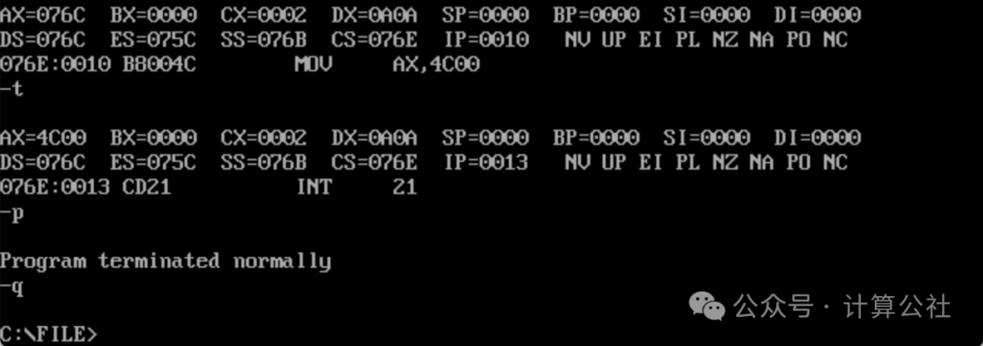
Thus, the step-by-step debugging is completed.