If you need to use the panel to synchronize the PLC’s time, you will need to use the “Date/Time” and “Job Mailbox” in the area pointer. For detailed explanations of “Date/Time” and “Job Mailbox”, please refer to the documentation for previous versions of WinCC Flexible.
Directory:
1 Introduction
2 Configuration Steps
2.1 Panel Program Configuration
2.2 PLC Program Configuration
2.3 Precautions
1 Introduction
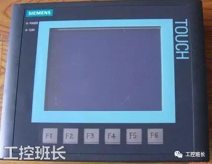
The new generation of Siemens Smart LINE V3 panels supports hardware clock functions. If you need to use the panel to synchronize the PLC’s time, you will need to use the “Date/Time” and “Job Mailbox” in the area pointer. For detailed explanations of “Date/Time” and “Job Mailbox”, please refer to the documentation for previous versions of WinCC Flexible.
It is assumed that the user is already familiar with the basic functions of WinCC Flexible software and STEP 7-Micro/WIN SMART software before reading this document.
The test environment is as follows:
Software Version:
WinCC Flexible SMART V3
STEP 7-Micro/WIN SMART
Hardware:
SMART 1000IE V3
CPU SR40
2 Configuration Steps
2.1 Panel Program Configuration
Activate “Date/Time” and “Job Mailbox” under the options for each connected “Area Pointer” and configure the corresponding address parameters as shown below:
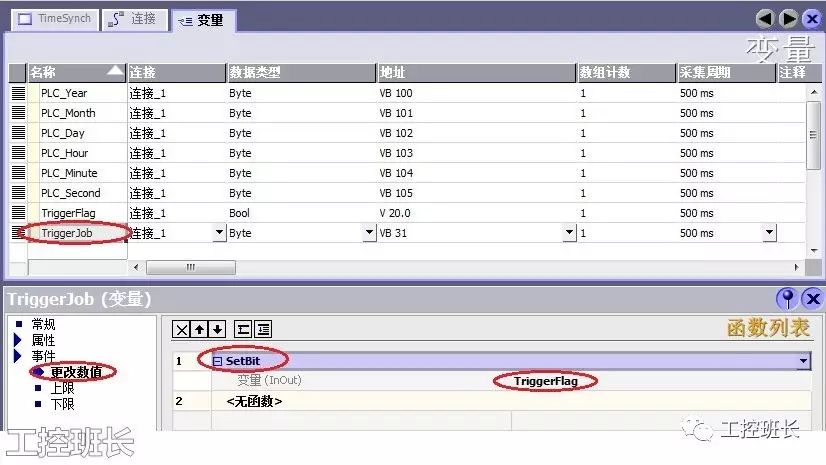
Figure 2-1 Area Pointer Configuration
Create the necessary variables. Create a Bool type variable “TriggerFlag” with the address V20.0. Create a Byte type variable “TriggerJob” with the address VB31. At the same time, create Byte type variables to display the time after PLC synchronization as shown below:
Figure 2-2 Create Necessary Variables
Regarding the meanings of each parameter in the “Job Mailbox” and “Date/Time”. As shown below:
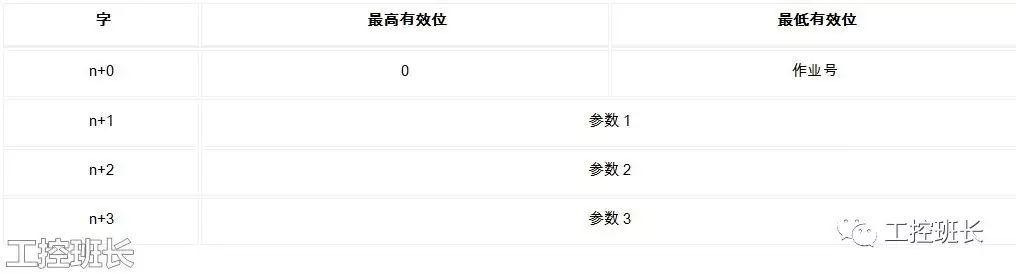
Figure 2-3 Job Mailbox
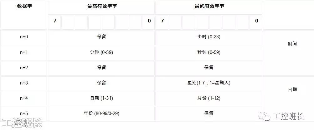
Figure 2-4 Date/Time
Create a screen and create an IO field to display the synchronized PLC clock. Note that the format type of the IO field needs to be set to “Hexadecimal”, and the format style set to “FF”. As shown below:
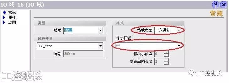
Figure 2-5 IO Format Style
Add a button on the screen, and under the button’s event, call the “SetValue” function to assign the value of the variable “TriggerJob” to 41. This is used to send the current date and time from the panel to the PLC. As shown below:
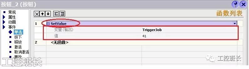
Figure 2-6 Button Event
2.2 PLC Program Configuration
In the PLC, use the address V20.0 as the trigger condition to implement the formatting conversion of the date and time and the setting of the PLC clock. To verify the result, the READ_RTC function is called periodically to read the PLC clock information into the storage area starting from VB100. This is used to display the PLC clock information on the host computer. As shown below:
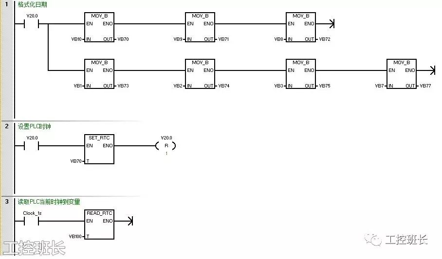
Figure 2-7 PLC Program Data Area Definition and Explanation
2.3 Precautions
The starting address defined in the panel program’s “Date/Time” is VW0. The corresponding addresses for year, month, day, hour, minute, second, and week are: VB10, VB9, VB8, VB1, VB2, VB3, VB7.
In S7-200, the time parameter address in SET_RTC is VB70. The corresponding addresses for year, month, day, hour, minute, second, and week are: VB70, VB71, VB72, VB73, VB74, VB75, VB77.
Therefore, adjustments to the date format are necessary. When setting the system time for S7-200, do not assign a “0” value to the “Week” byte in the time information; a specific “day of the week” must be provided, or this byte should be set to a constant 1. There should be at least a 5-second interval between two consecutive jobs; otherwise, the HMI device will be overloaded. Therefore, you will not see the synchronization result until about 5 seconds after clicking the button.
Additionally, the READ_RTC function is called to read the PLC clock into VB100, and a variable is created in the panel program to display the PLC clock, merely to verify the synchronization effect. If this is not needed, please ignore it.
Disclaimer: This article is a network reprint or adaptation, and the copyright belongs to the original author. If there are any copyright issues, please contact for deletion!
Industrial Control Class Leader QQ: 251087210 (same as personal WeChat)
Scan to follow the Industrial Control Class Leader’s WeChat public account