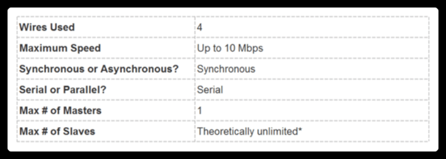
1. Comparison of Communication Speeds: SPI, I2C, UART
SPI > I2C > UART
1. Synchronous communication > Asynchronous communication; 2. In synchronous communication, a clock line must connect both ends of the transmission; 3. All are serial communication methods, while parallel communication is used for internal storage communication, such as flash; 4. The suitable transmission distance is inversely proportional to the communication speed.
3-SPI: Two combined data lines, 1 clock line, 1 CS (Chip Select line) SPI: 2 data lines, 1 clock line, 1 CS (Chip Select line) / Serial Synchronous Full Duplex Communication I2C: 1 data line, 1 clock line / Serial Synchronous Half Duplex Communication, transmission distance shorter than UART UART: 2 data lines, 1 ground line / Serial Asynchronous Full Duplex Communication, transmission distance longer than I2C
(The I2C interface is an “inter-device” interface, used for data transmission within a single board) (UART is a “device-to-device” interface, more commonly used for data transmission between two devices)
2. Differences Between Serial and Parallel, Synchronous and Asynchronous:
Serial communication: Uses a single data line to transmit data bit by bit, characterized by simple communication lines, low cost, suitable for long-distance transmission. Parallel communication: Uses multiple data lines to transmit data bits simultaneously, characterized by fast transmission speed, suitable for short-distance transmission.
Asynchronous: Maintains synchronization within the transmission time of a character. Synchronous: Requires a clock line for synchronization during data transmission, such as IIC bus, SPI bus.
3. Differences Between I2C Interface and Serial Interface:
I2C is a two-wire serial bus, while UART is a universal asynchronous transceiver serial port. UART is a serial asynchronous communication interface, which includes RS232, RS499, RS423, RS422, and RS485 interface specifications and standards, meaning UART is a general term for serial asynchronous communication ports.
There are significant differences in methods. For example, I2C is address-based communication, supporting multi-party communication, which serial ports cannot handle; the communication mechanisms and principles of the two are also different; additionally, I2C is relatively faster, as it was invented by Philips to solve speed bottlenecks. There is a lot of information available online, feel free to search for it!
1. The I2C interface is an “inter-device” interface, used for data transmission within a single board, while the RS232 serial interface is a “device-to-device” interface, more commonly used for data transmission between two devices.
2. In terms of transmission distance, RS232 can transmit over longer distances, but I have not conducted specific experiments to determine the exact differences.
3. Serial ports transmit data over one line and receive data over another line. I2C has one clock line and one data line, where the data line is bidirectional, capable of both receiving and sending.
4. Different protocols, different baud rates.
Serial interfaces, like microcontrollers, have the clock provided by the internal MCU, while the I2C interface must be determined by the device and cannot be too fast.
5. I2C is synchronous serial transmission, while RS232 (or UART, Universal Asynchronous Receiver Transmitter) is asynchronous serial transmission.
6. Synchronous methods must have a clock line connecting both ends of the transmission; the SCL in I2C is this clock line. Because synchronous methods do not incur additional overhead for data alignment, their transmission rates are generally higher than those of asynchronous methods.
4. Similarities and Differences Between Bus Interfaces: UART, I2C, SPI, USB
1. UART is a universal asynchronous serial port, not very fast, can be full duplex, generally consists of a baud rate generator, UART transmitter, and UART receiver, with hardware typically having two lines, one for receiving and one for transmitting.
2. SPI is a high-speed synchronous serial port, fast, can be full duplex, independent transmission and reception, synchronous interface, can connect multiple SPI devices, with hardware consisting of 4 lines.
3. I2C is a bidirectional, two-wire, serial, multi-master interface standard. It is not very fast, half duplex, synchronous interface, with a bus arbitration mechanism, very suitable for frequent data communication between devices over short distances, and can achieve device networking.
4. USB is a universal serial bus, high-speed, half duplex, consisting of a host, hub, and devices. Devices can connect to lower-level hubs to form a star structure.
5. Differences in Serial Communication: UART, SPI, I2C:
1. UART consists of two lines, one for sending and one for receiving, allowing for full duplex communication, with fewer lines. Data is transmitted asynchronously, with stricter timing requirements for both parties, and the communication speed is not very fast. It is most commonly used in multi-machine communication.
2. Compared to UART, the SPI interface has an additional synchronous clock line, and the timing requirements for both parties are not strict, allowing for easy integration between different devices, and the communication speed is very fast. It is generally used for high-speed data communication between internal components of products, such as large-capacity storage devices.
3. The I2C interface is also a two-wire interface, where data is transmitted between the two lines through complex logical relationships. The communication speed is not high, and programming can be relatively complicated. It is mainly used in microcontroller systems to connect with small EEPROMs like 24C02.
SPI: High-speed synchronous serial port. 3-4 line interface, independent transmission and reception, can be synchronous.
UART: Universal asynchronous serial port. Completes bidirectional communication at standard baud rates, slow speed.
SPI: A serial transmission method, three-wire system, with communication protocols and usage available online to achieve bidirectional data transmission through serial peripheral interfaces.
UART: Universal asynchronous transceiver.
UART is a chip used to control communication between computers and serial devices. One point to note is that it provides an RS-232C data terminal device interface, allowing computers to communicate with modems or other serial devices using RS-232C interfaces. As part of the interface, UART also provides the following functions:
1. Converts parallel data sent from the computer into an output serial data stream.
2. Converts incoming serial data from external sources into bytes for internal use by parallel data devices.
3. Adds parity bits to the output serial data stream and performs parity checks on the incoming data stream.
4. Adds start and stop markers to the output data stream and removes them from the received data stream.
5. Handles interrupt signals from keyboards or mice (keyboards and mice are also serial devices).
6. Can manage synchronization issues between the computer and external serial devices.
7. Some higher-end UARTs also provide input/output data buffers. The newer UART is the 16550, which can store 16 bytes of data in its buffer before the computer needs to process it, while the typical UART is the 8250.
8. If you purchase an internal modem now, it will typically have a 16550 UART inside.
I2C: Can replace standard parallel buses, connecting various integrated circuits and functional modules. I2C is a multi-master bus, so any device can act as a master controller and control the bus. Each device on the bus has a unique address, and depending on their capabilities, they can function as transmitters or receivers. Multiple microcontrollers can coexist on the same I2C bus.
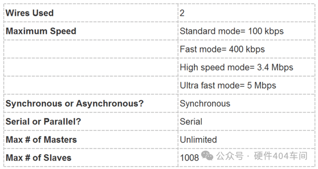
I2C Bus: The main advantage of the I2C bus is its simplicity and efficiency. Since the interface is directly on the components, the I2C bus occupies very little space, reducing the space on the circuit board and the number of chip pins, lowering interconnection costs. The bus length can reach up to 25 feet and can support up to 40 components at a maximum transmission rate of 10Kbps. Another advantage of the I2C bus is that it supports multi-mastering, where any device capable of sending and receiving can become the master bus. One master can control the signal transmission and clock frequency. Of course, only one master can be active at any given time.
UART:
Single-ended, long-distance transmission. Most computers contain two RS232-based serial ports. Serial ports are also a common communication protocol for instrumentation devices; many GPIB-compatible devices also have RS-232 ports. Serial communication protocols can also be used to obtain data from remote acquisition devices. The concept of serial communication is quite simple; serial ports send and receive bytes bit by bit. Although slower than parallel communication, serial ports can send data using one line while receiving data on another line. It is simple and capable of long-distance communication. For example, IEEE488 defines that the length of parallel communication lines must not exceed 20 meters, and the length between any two devices must not exceed 2 meters; while for serial ports, the length can reach up to 1200 meters. The specific applicable range is much broader, including military, medical, etc.
The first difference is, of course, the names: SPI (Serial Peripheral Interface); I2C (INTER IC BUS); UART (Universal Asynchronous Receiver Transmitter).
The second difference lies in the electrical signal lines:
The SPI bus consists of three signal lines: Serial Clock (SCLK), Serial Data Output (SDO), and Serial Data Input (SDI). The SPI bus can connect multiple SPI devices. The SPI device providing the serial clock is the SPI master, while other devices are SPI slaves. Full duplex communication can be achieved between master and slave devices, and when there are multiple slaves, an additional slave select line can be added.
If using general IO ports to simulate the SPI bus, it must have one output port (SDO), one input port (SDI), and another port depending on the type of device being implemented. If implementing master-slave devices, input and output ports are needed; if only implementing a master device, only an output port is needed; if only implementing a slave device, only an input port is needed.
The I2C bus is a bidirectional, two-wire (SCL, SDA), serial, multi-master interface standard, with a bus arbitration mechanism, very suitable for close-range, non-frequent data communication between devices. In its protocol system, data transmission always includes the address of the target device, allowing for device networking. If using general IO ports to simulate the I2C bus and achieve bidirectional transmission, one input/output port (SDA) is needed, along with one output port (SCL). (Note: I have limited knowledge about I2C, and this description may be incomplete.)
The UART bus is an asynchronous serial port, generally more complex than the previous two synchronous serial structures, typically consisting of a baud rate generator (the generated baud rate is 16 times the transmission baud rate), UART receiver, and UART transmitter, with hardware consisting of two lines, one for sending and one for receiving. Clearly, if using general IO ports to simulate the UART bus, one input port and one output port are needed.
The third difference, as seen from the second point, is that SPI and UART can achieve full duplex, while I2C cannot.
The fourth, let’s see what the experts say!
wudanyu: I think I2C is more powerful than UART and SPI because it has fewer lines, but it is also technically more complicated, as I2C requires support for bidirectional IO and uses pull-up resistors, which I believe makes it less resistant to interference, generally used for communication between chips on the same board, and less often for long-distance communication. SPI is simpler to implement, while UART requires a fixed baud rate, meaning the intervals between two bits of data must be equal, while SPI does not have such requirements because it is a clocked protocol.
quickmouse: I2C is slightly slower than SPI, the protocol is a bit more complex than SPI, but it requires fewer connections than standard SPI.
Now let’s start with some simple concepts:
Serial vs Parallel
Electronic devices communicate by sending data bits. A bit is binary, either 1 or 0. Bits are transmitted from one device to another through rapid voltage changes. In a 5V system, “0” is communicated through a short pulse of 0V, while “1” is communicated through a short pulse of 5V.
Data bits can be transmitted in parallel or serial form. In parallel communication, data bits are transmitted simultaneously on the lines. The following diagram shows the parallel transmission of the letter “C” in binary (01000011):
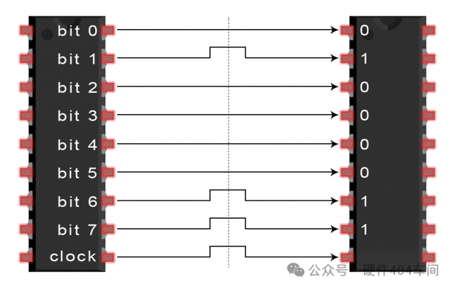
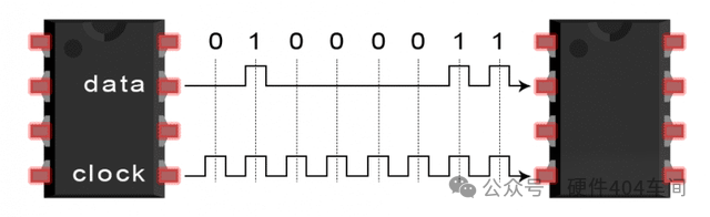
In serial communication, bits are sent one by one over a single line. The following diagram shows the serial transmission of the letter “C” in binary (01000011):
SPI Communication
SPI is a common general communication protocol for devices. It has a unique advantage of being able to transmit data without interruption, allowing for continuous sending or receiving of any number of bits. In contrast, I2C and UART send data in packets, with a limited number of bits.
In SPI devices, devices are divided into master and slave systems. The master is the controlling device (usually a microcontroller), while the slave (usually a sensor, display, or storage chip) receives instructions from the master.
A complete SPI communication consists of four signal lines: MOSI (Master Output/Slave Input) – signal line, master output, slave input. MISO (Master Input/Slave Output) – signal line, master input, slave output. SCLK (Clock) – clock signal. SS/CS (Slave Select/Chip Select) – chip select signal.
Characteristics of SPI Protocol
In fact, the number of slaves is limited by the system load capacitance, which reduces the master’s ability to switch accurately between voltage levels.
Working Principle
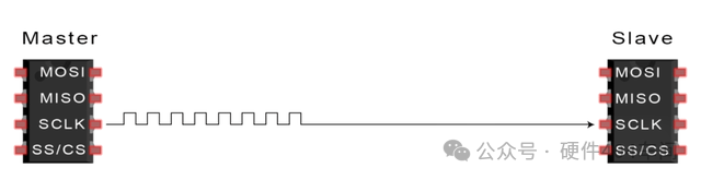
Clock Signal
Each clock cycle transmits one bit of data, so the speed of data transmission depends on the frequency of the clock signal. The clock signal is generated by the master, so SPI communication is always initiated by the master.
Any communication protocol that shares a clock signal is called synchronous. SPI is a synchronous communication protocol, while some asynchronous communications do not use a clock signal. For example, in UART communication, both sides are set to a pre-configured baud rate, which determines the speed and timing of data transmission.
Chip Select Signal
The master enables communication by pulling the slave’s CS/SS low. In idle/non-transmission states, the chip select line remains high. The master can have multiple CS/SS pins, allowing it to communicate with multiple different slaves.
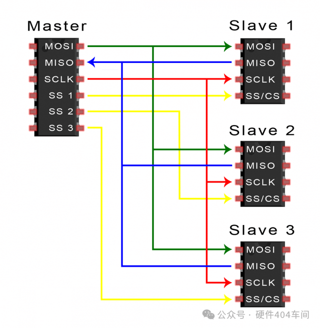
If the master has only one chip select pin available, the following method can be used to connect these slave devices:
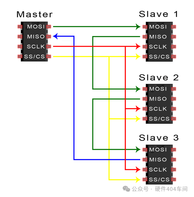
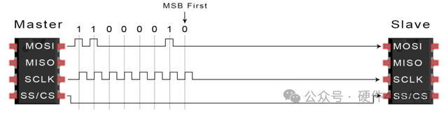
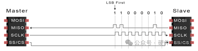
MOSI and MISO
The master sends data to the slave serially via MOSI, and the slave can also send data back to the master via MISO, allowing both to occur simultaneously. Thus, theoretically, SPI is a full duplex communication protocol.
Transmission Steps
1. The master outputs the clock signal.
2. The master pulls the SS/CS pin low to activate the slave.

3. The master sends data to the slave via MOSI.
4. If a response is needed, the slave sends data back to the master via MISO.
Using SPI has some advantages and disadvantages; when choosing between different communication protocols, it should be considered based on project requirements.
Advantages and Disadvantages
Advantages
SPI communication has no start or stop bits, allowing for continuous data flow without interruption; it does not have a complex slave addressing system like I2C, and the data transmission rate is higher than I2C (almost twice as fast). Independent MISO and MOSI lines allow for simultaneous sending and receiving of data.
Disadvantages
SPI uses four lines (I2C and UART use two lines), lacks confirmation of successful signal reception (I2C has this feature), and has no form of error checking (like parity bits in UART).

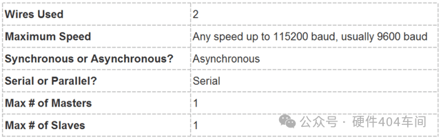
UART stands for Universal Asynchronous Receiver/Transmitter, also known as serial communication. It is not a communication protocol like SPI and I2C, but rather a physical circuit or independent IC within a microcontroller.
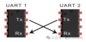
The main purpose of UART is to send and receive serial data, and its best advantage is that it only uses two lines to transmit data between devices. The principle of UART is easy to understand, but if you have not read about the SPI communication protocol, that might be a good starting point.
UART Communication
In UART communication, two UARTs communicate directly with each other. The sending UART converts parallel data from the controlling device (such as a CPU) into serial form and sends it to the receiving UART. Only two lines are needed to transmit data between the two UARTs, with data flowing from the Tx pin of the sending UART to the Rx pin of the receiving UART:
UART belongs to asynchronous communication, meaning there is no clock signal; instead, start and stop bits are added to the data packets. These bits define the beginning and end of the data packet, allowing the receiving UART to know when to read the data.
When the receiving UART detects the start bit, it reads the bits in the data frame at a specific baud rate. The baud rate is a measure of data transmission speed, expressed in bits per second (bps). The two UARTs must operate at approximately the same baud rate, with a maximum difference of about 10%.
Working Principle
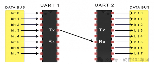
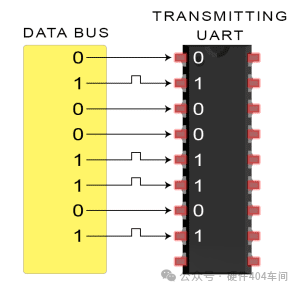
The sending UART retrieves parallel data from the data bus, adds a start bit, a parity bit, and a stop bit to form a data packet, and serially outputs it from the Tx pin, while the receiving UART reads the data packet bit by bit from its Rx pin.
UART data includes 1 start bit, 5 to 9 data bits (depending on the UART), an optional parity bit, and 1 or 2 stop bits:
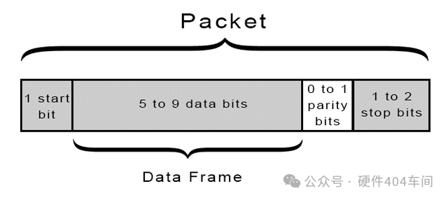
Start Bit:
The UART data transmission line typically remains at a high voltage level when not transmitting data. When starting transmission, the sending UART pulls the transmission line from high to low voltage within one clock cycle. When the receiving UART detects this transition from high to low voltage, it begins reading the bits in the data frame at the baud rate.
Data Frame:
The data frame contains the actual data being transmitted. If using a parity bit, it can be 5 bits, up to 8 bits. If not using a parity bit, the length of the data frame can be 9 bits.
Parity Bit:
The parity bit is a way for the receiving UART to determine if any data changes occurred during transmission. After reading the data frame, the receiving UART counts the number of bits with a value of 1 and checks whether the total is even or odd, and whether it matches the data.
Stop Bit:
To signal the end of the data packet, the sending UART drives the data transmission line from low voltage to high voltage for at least two bit times.
Transmission Steps
1. The sending UART receives parallel data from the data bus:
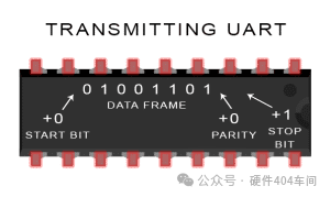
2. The sending UART adds the start bit, parity bit, and stop bit to the data frame:
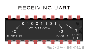
3. The entire data packet is serially sent from the sending UART to the receiving UART. The receiving UART samples the data line at the pre-configured baud rate:

4. The receiving UART discards the start bit, parity bit, and stop bit from the data frame:
5. The receiving UART converts the serial data back into parallel data and transmits it to the data bus of the receiving end:

Advantages and Disadvantages
Advantages
Only uses two wires, no clock signal, has parity bits for error checking, and as long as both sides set the data packet structure correctly, it is a well-documented and widely used method.
Disadvantages
The maximum size of the data frame is 9 bits, does not support multiple slave systems or multiple master systems, and the baud rate of each UART must be within 10% of each other.
I2C Communication
The I2C bus is a simple, bidirectional, two-wire synchronous serial bus developed by Philips. It only requires two wires to transmit information. It combines the advantages of SPI and UART, allowing multiple slaves to connect to a single master (like SPI), and also allows multiple masters to control one or more slaves. This is very useful when you want multiple microcontrollers to log data to a single storage card or display text on a single LCD.
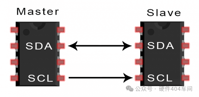
SDA (Serial Data) – Data line.
SCL (Serial Clock) – Clock line.
I2C is a serial communication protocol, so data is transmitted bit by bit along the SDA. Like SPI, I2C also requires a clock synchronization signal, and the clock is always controlled by the master.
Working Principle
Data transmission in I2C occurs in the form of multiple messages, each containing the binary address frame of the slave, one or more data frames, as well as start and stop conditions, read/write bits, and ACK/NACK bits between data frames:

Start Condition: When SCL is high, SDA switches from high to low.
Stop Condition: When SCL is high, SDA switches from low to high.

Address Frame: A unique 7-bit or 10-bit sequence for each slave device, used for address identification between master and slave devices.
Read/Write Bit: A bit that indicates whether the master is sending data to the slave (low) or requesting data (high).
ACK/NACK: Each frame in the message is followed by an ACK/NACK bit. If the address frame or data frame is successfully received, the receiving device returns an ACK bit to indicate confirmation.
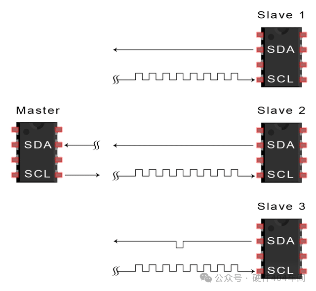
Addressing
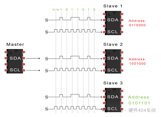
Since I2C does not have a chip select line like SPI, it needs to use another method to confirm a specific slave device, which is addressing.
The master sends the address of the slave it wants to communicate with to each slave, and each slave compares it with its own address. If the address matches, it sends a low-level ACK bit back to the master. If it does not match, it does nothing, and the SDA line remains high.
Read/Write Bit
The end of the address frame contains a read/write bit. If the master is sending data to the slave, it is low. If the master is requesting data from the slave, it is high.
Data Frame
Once the master detects the ACK bit from the slave, it can send the first data frame. The data frame is always 8 bits, followed by an ACK/NACK bit to verify the reception status. After sending all data frames, the master can send a stop condition to terminate communication.
Transmission Steps
1. When the SCL line is high, the master initiates bus communication by switching the SDA line from high to low.
2. The master sends the 7-bit or 10-bit address of the slave it wants to communicate with, along with the read/write bit:
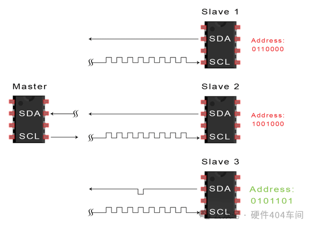
3. Each slave compares the address sent by the master with its own address. If the address matches, the slave returns an ACK bit by pulling the SDA line low. If the master’s address does not match the slave’s address, the slave keeps the SDA line high.
4. The master sends or receives data frames:
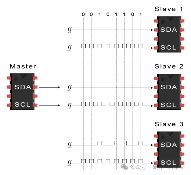
5. After each data frame is transmitted, the receiving device returns another ACK bit to the sender to confirm successful reception of that frame:
6. The master then switches the SCL to high and subsequently switches the SDA to high, sending a stop condition to the slave.
Single Master vs Multiple Slaves
Since I2C uses addressing, a single master can control multiple slaves. When using a 7-bit address, up to 128 (2^7) unique addresses can be used. Using a 10-bit address is uncommon but can provide 1,024 (2^10) unique addresses. When connecting multiple slaves to a single master, use 4.7K ohm pull-up resistors to connect them, for example, connecting the SDA and SCL lines to Vcc:

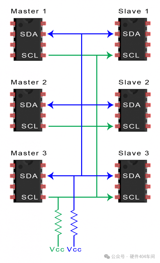
Multiple Masters vs Multiple Slaves
I2C supports multiple masters connected to multiple slaves. When two masters attempt to send or receive data simultaneously via the SDA line, issues can arise. Therefore, each master must check the SDA line to see if it is low or high before sending a message. If the SDA line is low, it means another master is controlling the bus. If the SDA line is high, it is safe to send data. When connecting multiple masters to multiple slaves, use 4.7K ohm pull-up resistors to connect the SDA and SCL lines to Vcc:
Advantages and Disadvantages
Compared to other protocols, I2C may sound complex. Here are some advantages and disadvantages to help you determine if they fit your project needs:
Advantages
Only uses two wires, supports multiple masters and multiple slaves, hardware is simpler than UART, and it is a well-known and widely used protocol.
Disadvantages
Data transmission rate is slower than SPI, and the size of data frames is limited to 8 bits.