The above ☝️☝️☝️ is about a food-related public account, where each recipe has detailed steps and high-definition images, making it easy for kitchen novices to get started. Follow it to unlock more delicious recipes and fill your meals throughout the seasons with surprises!
1. What are the characteristics of SPI communication?
SPI communication, or Serial Peripheral Interface, is a high-speed, full-duplex, synchronous communication bus commonly used for communication between microcontrollers and peripherals. Its characteristics are as follows:

(1) Simple hardware structure
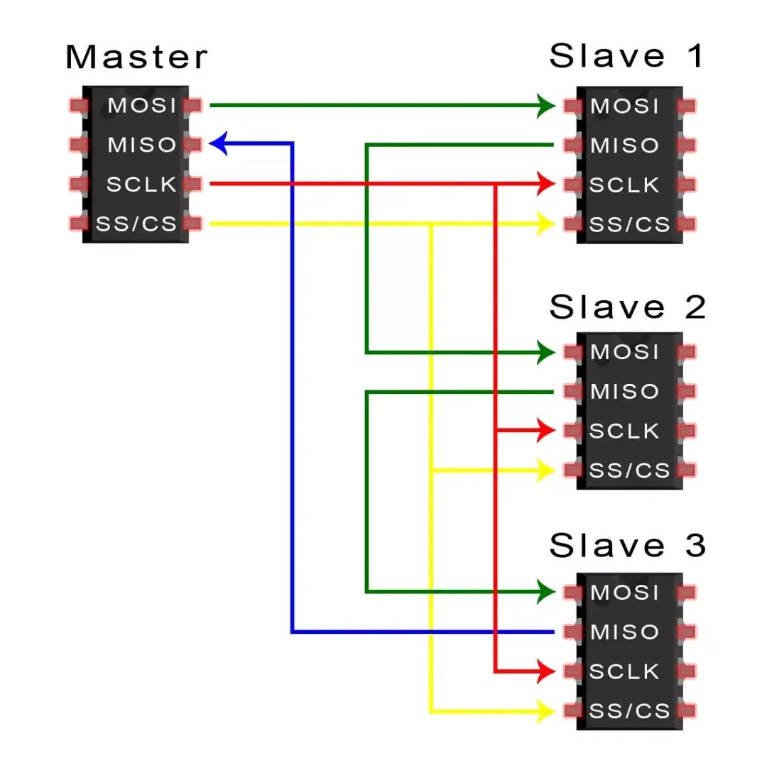
Fewer connections: Typically, only 4 wires are needed, namely the clock line (SCK), master output slave input line (MOSI), master input slave output line (MISO), and chip select line (CS), to achieve data transmission between the master and slave devices, thus saving hardware resources and circuit board space.Easy to implement: Master and slave devices only need to have an SPI controller and related pins, with no complex circuit design required. Many microcontrollers and peripherals integrate SPI interfaces for convenient connection and communication.(2) Fast communication speedHigh-speed clock support: The SPI communication clock frequency is relatively high, reaching tens of MHz, which can meet the demand for high-speed data transmission, such as reading and writing data between flash memory chips and master control chips, which can be completed quickly.Full-duplex transmission: Data can be transmitted bidirectionally between the master and slave devices simultaneously. When the master sends data, the slave can simultaneously return data, improving communication efficiency. For example, in audio codec applications, audio data and control information can be transmitted simultaneously.(3) Flexible data transmissionConfigurable as needed: Data frame format, transmission bit width, etc., can be configured according to requirements, usually supporting various data widths such as 8-bit and 16-bit, which can adapt to the data format requirements of different peripherals, such as when communicating with image sensors of different resolutions.Supports multiple device connections: The master can select different slave devices for communication through the chip select line, achieving a one-master-multiple-slave communication architecture, which is convenient for expanding system functionality. For example, in smart home appliance control systems, multiple sensors and actuators can be connected.(4) Higher reliabilitySynchronous transmission mechanism: Data transmission is synchronized using clock signals, and the master and slave devices send and receive data according to a unified clock rhythm, ensuring the accuracy and stability of data transmission and reducing transmission errors.No acknowledgment mechanism: SPI communication does not have a dedicated acknowledgment signal, but errors can be detected during data transmission through checksums, cyclic redundancy checks (CRC), etc. If errors are found, retransmission can ensure data integrity.2. How do the master and slave transmit data in SPI communication?
(1) Initialization phaseConfiguring the SPI controller: The master first configures its SPI controller, including setting clock frequency, data bit width, transmission mode, etc. The slave must also configure related parameters to ensure consistency with the master for normal communication.Chip select operation: The master selects the slave to communicate via the chip select line (CS), pulling the corresponding slave’s CS pin low, activating that slave to prepare to receive and send data, while unselected slaves remain in a high-impedance state and do not participate in communication.(2) Data transmission phaseClock synchronization: The master’s SPI controller generates a clock signal (SCK) and sends it to the slave via the clock line. The master and slave devices sample and send data based on the rising or falling edge of this clock signal, ensuring synchronized data transmission.Data sending: When the master sends data, it sends the data bit by bit from the master output slave input line (MOSI). The slave receives the data on the MOSI line bit by bit under the control of the clock signal and stores it in its own receive buffer.Data receiving: When the slave needs to send data back to the master, it sends data bit by bit from the master input slave output line (MISO). The master receives the data bit by bit from the MISO line under the influence of the clock signal and stores it in its own receive buffer.(3) Transmission end phaseChip select recovery: After data transmission is complete, the master pulls the chip select line (CS) high, releasing the slave, which then enters an idle state and no longer communicates with the master.Data processing: The master and slave separately process the data in their receive buffers. For instance, the master may store, analyze, or use the received data for subsequent control operations, while the slave may execute corresponding tasks based on the received commands.
3. Clock polarity (CPOL) and clock phase (CPHA) in SPI communication?
(1) Clock polarity (CPOL)Definition: Refers to the idle state level of the SPI clock signal (SCK).Values and impact: When CPOL=0, SCK is low when idle, and data is sampled on the rising edge of SCK, with data changing on the falling edge; when CPOL=1, SCK is high when idle, and data is sampled on the falling edge of SCK, with data changing on the rising edge.(2) Clock phase (CPHA)Definition: Refers to the relative relationship between data sampling and clock signal, determining which edge of the clock cycle data is sampled and when data is output to the bus.Values and impact: When CPHA=0, data is sampled on the first edge of SCK (depending on CPOL, it could be the rising or falling edge) and data transmission occurs on the second edge; when CPHA=1, data is sampled on the second edge of SCK and data transmission occurs on the first edge.(3) Combined modesBy combining different values of CPOL and CPHA, there are four operating modes for SPI communication.
For example, mode 0 is CPOL=0, CPHA=0;
Mode 1 is CPOL=0, CPHA=1;
Mode 2 is CPOL=1, CPHA=0;
Mode 3 is CPOL=1, CPHA=1.
The master and slave devices must operate in the same mode for normal communication.
4. In SPI communication with multiple slaves, how to select different slaves?
(1) Independent control of chip select lines (CS)Hardware connection: The master assigns an independent chip select line for each slave, with each slave’s chip select pin connected to different GPIO pins on the master.Working principle: The master pulls down the chip select line corresponding to the slave it needs to communicate with, while the chip select lines of other slaves remain high, in an unselected state, allowing only the selected slave to communicate with the master.(2) Decoder methodHardware connection: A decoder is used to generate chip select signals. Several GPIO pins of the master are connected to the input of the decoder, and the output of the decoder is connected to the chip select pins of each slave.Working principle: The master inputs different coded signals to the decoder, which then selects the corresponding output pin based on the input code, thus selecting the appropriate slave.(3) Software protocol methodProtocol definition: Define specific slave selection instructions or address codes in the SPI communication protocol.Working principle: Before sending data, the master first sends a data frame containing the slave address or selection instruction. All slaves receive this data frame and check whether the address or instruction matches their own. If it matches, the slave considers itself selected and begins data interaction with the master; if not, it ignores subsequent data.(3) Daisy chain methodHardware connection: All slaves are connected in series, with the master’s SPI interface connected to the first slave, the output of the first slave connected to the input of the second slave, and so on.

Working principle: When the master sends data, the data first enters the first slave. Each slave, upon receiving the data, determines whether it is addressed based on the data’s address or instruction.
If it is, it processes accordingly and passes the data on; if not, it simply passes the data on. In this way, the master can communicate with any slave in the chain.