I2C is a widely used bus, generally used to connect various slave devices, such as EEPROM memory, temperature and humidity sensors, gyroscopes, etc.Mastering I2C is considered a fundamental skill, and it is essential for newcomers in the industry to learn it systematically.1. A Brief History of I2C
In 1980, Philips began developing a communication bus to connect various low-speed devices (Philips chips).
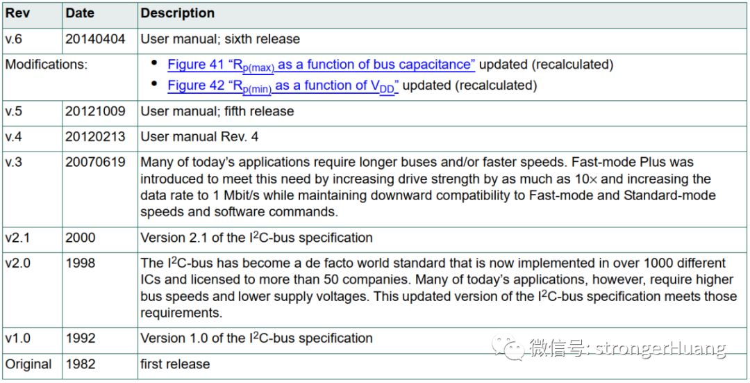
In 1982, the original version was released, using a communication speed of 100KHz, providing 7-bit addressing, limiting the number of devices on the bus to 112 (with a few reserved addresses).
In 1992, the first specification was released, adding a fast mode of 400kHz and an extended 10-bit address space.
In 1998, with advancements in technology, the communication speed requirements increased to high-speed 3.4 MHz, later upgraded to 5MHz, while using differential signaling to improve noise immunity.
History of I2C versions:
Additional Note on SMBus:
In 1995, Intel introduced a variant based on I2C called the “System Management Bus” (SMBus). SMBus is a more strictly controlled format designed to maximize the predictability of communication between ICs supported on PC motherboards.
The most significant difference between SMBus and I2C is that it limits the speed to between 10kHz and 100kHz, while I2C can support devices from 0kHz to 5MHz.
2. Basic Content of I2C
I²C: Inter-Integrated Circuit, literally meaning between integrated circuits, is the abbreviation for I²C Bus.
I2C requires only two wires, which can support up to 1008 slave devices, enabling synchronous serial communication.
Unlike SPI, I2C can support multiple masters and multiple slaves on the bus.
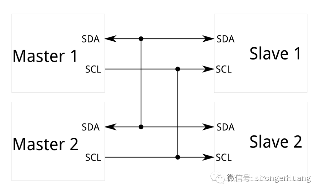
1. I2C Two-Wire Signals
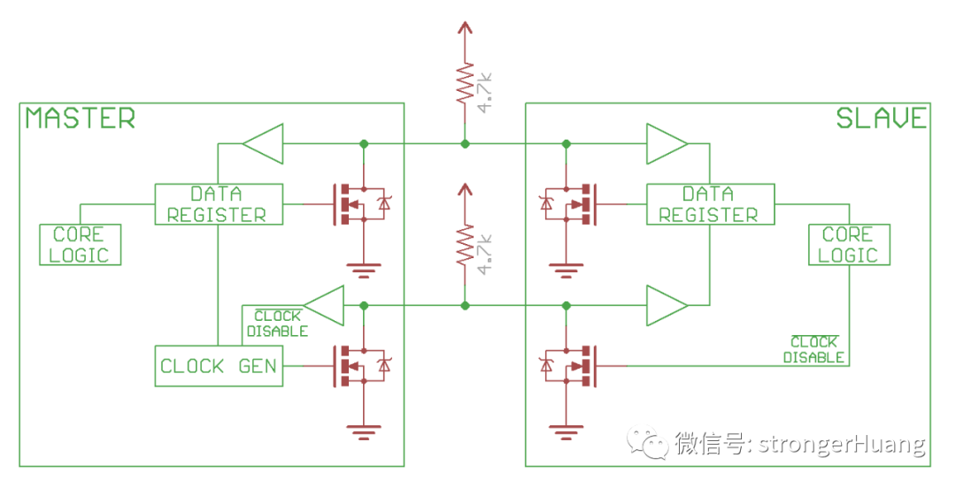
Each I2C bus consists of two signals: SCL clock signal and SDA data signal. The clock signal is always generated by the current bus master.
Unlike UART and SPI, the I2C bus drivers are open-drain (if you are unfamiliar with open-drain, please search for it), meaning they can pull the corresponding signal line low but cannot drive it high.
Each signal line has a pull-up resistor that restores the signal to high when no device pulls it low.
2. Signal Levels
Typically, I2C bus signal levels are mostly 5V and 3.3V. If the devices on the bus are compatible with these two levels, they can be used directly.
If the signal voltage differs significantly (for example, 5V and 2.5V), or if the levels are incompatible, level shifting is required.
3. I2C Protocol
The challenge for beginners with I2C lies in understanding the protocol, which can be explained from a few simple perspectives.
1. Basic Transmission Principles
I2C has two buses: SCL clock signal and SDA data signal.SCL is generated by the master, while SDA can be generated by either the master or the slave.
I2C is synchronous serial communication and is classified as half-duplex, meaning that at any given time, SDA can only send signals from one device.
Thus, you will find that the signals (data) on SDA are sometimes from the master and sometimes from the slave.
2. Basic Protocol: 7/10-bit Addressing
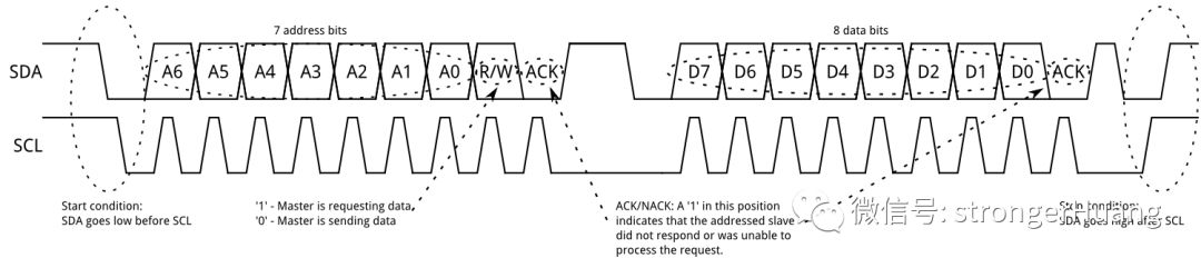
I2C supports 7-bit and 10-bit addressing, with messages primarily divided into two types: address and data.
7-bit Address:
10-bit Address:
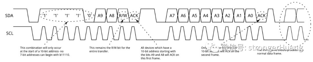
In addition to address and data, there are start conditions, stop conditions, read/write, and acknowledgment information (described in small text in the images above).
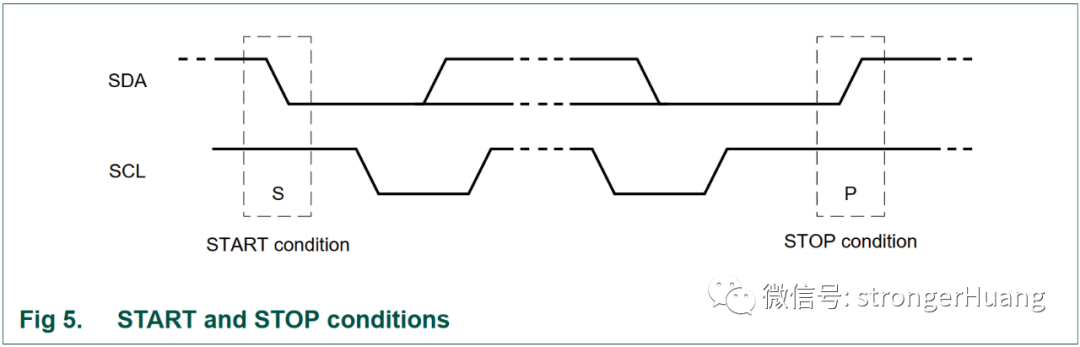
3. Start and Stop Conditions
The SDA data line transitioning from high to low indicates a start condition on the bus;
The SDA data line transitioning from low to high indicates a stop condition on the bus;
4. Acknowledgment (ACK) and Non-Acknowledgment (NACK)
Acknowledgment and non-acknowledgment occur after each byte, where the receiver sends a confirmation signal to the sender, indicating that the “data” has been successfully received and that the next byte of data can be sent.
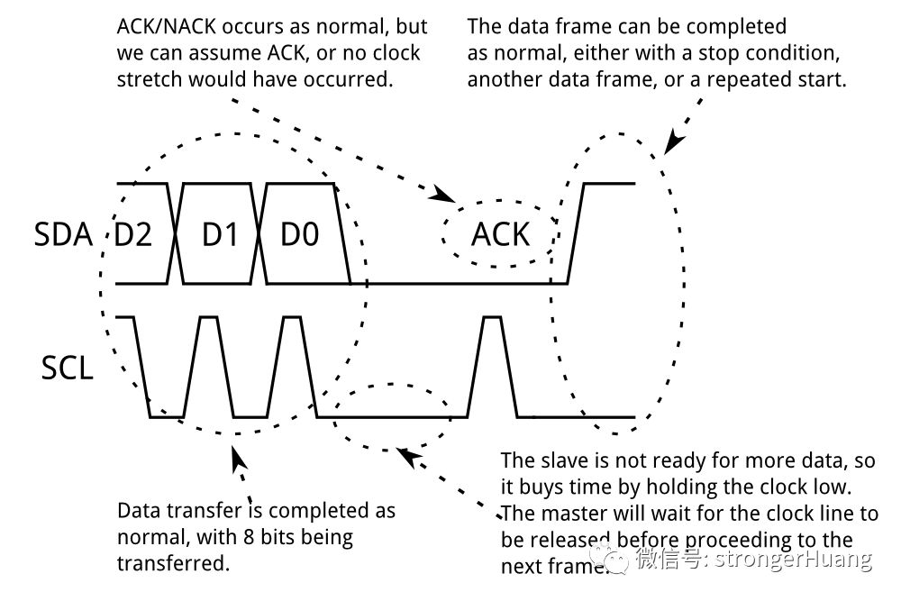
There are many situations for acknowledgment; beginners can refer to the protocol manual, which provides detailed explanations.
5. More Protocol Content
Address of the I2C protocol manual:
https://www.nxp.com/docs/en/user-guide/UM10204.pdf
END
Disclaimer:This article is authorized by the author and reprinted from the “strongerHuang” public account. The reprint is for learning reference only and does not represent this account’s endorsement of its views. This account also does not bear any infringement liability for its content, text, or images. For group discussions, submissions, or collaborations, please add WeChat (WeChat ID: mianbaoban).
Follow the Breadboard Community for daily selections of electronic technology knowledge
▼

-
【Show Your Board】Soldered nearly 40 boards, made a high-voltage power supply
-
I ran neural network algorithms on the STM32 microcontroller
-
Don’t use GD32? I replaced STM32 with the domestic MM32
-
【Show Your Board】OneWatch watch (chip selection + schematic)
-
RS-485 bus, this article is very detailed
-
Painful pitfalls in “battery voltage detection circuit”, a tearful summary of design points