The SPI protocol is a commonly used high-speed, full-duplex, synchronous serial communication protocol, widely used for data exchange with sensors (such as temperature sensors, pressure sensors, etc.), data storage and retrieval from storage devices (such as EEPROM, FLASH memory), control of display modules (such as LCD screens, OLED screens, etc.), communication with wireless communication modules (such as Wi-Fi, Bluetooth, etc.), and data exchange with audio codecs (such as ADC, DAC, etc.). Typically, data exchange is conducted using four lines (SS/CS, MOSI, MISO, SCK).
Main Features:
1. Full-duplex communication: SPI communication allows data to be sent and received simultaneously, with data transmission occurring on both the MOSI and MISO lines.
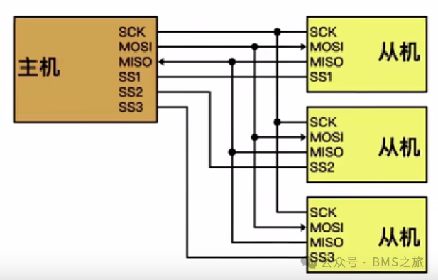
2. Supports multiple slave device configurations: The master device specifies a particular slave device for communication using the chip select signal SS/CS, enabling one master to communicate with multiple slaves.
3. Suitable for short-distance transmission with high communication speed: The clock frequency of SPI communication is relatively high, meeting the demands for high-speed transmission.
4. No acknowledgment mechanism: SPI communication does not have an acknowledgment signal, but the accuracy of information can be verified through cyclic redundancy checks and other methods.

Physical Layer
1. SCK (Serial Clock): The clock signal generated by the master device.
2. MOSI (Master Out Slave In): The data line for master output/slave input, used for the master device to send data.
3. MISO (Master In Slave Out): The data line for master input/slave output, used for the master device to receive data.
4. SS/CS/NSS (Slave Select): The chip select signal controlled by the master device, used to specify communication with a particular slave device. A master device typically connects to one or more slave devices; unlike I2C communication, which selects slave devices via address lines, SPI communication uses chip select signals for selection. Typically, pulling the chip select signal low indicates selection for communication with that slave device.
Protocol Layer
Basic SPI Communication Process:
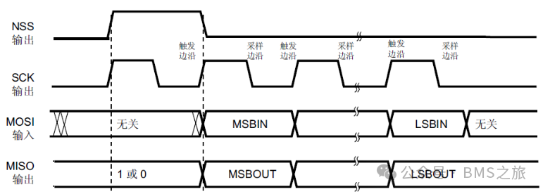
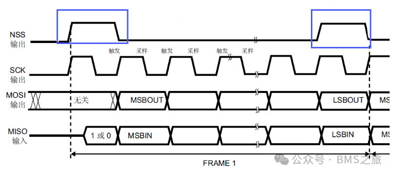
This is the communication timing of a host, where NSS, SCK, and MOSI are generated by the master device, while MISO is generated by the slave device. Communication begins when the NSS chip select signal is pulled low. During one cycle of SCK, MOSI and MISO transmit one bit.
Communication Modes
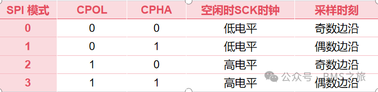
There are four communication modes in SPI, defined by the combinations of clock polarity (CPOL) and clock phase (CPHA).
Clock polarity defines the level signal when the clock is in an idle state.
When CPOL=0, it indicates that when SCLK=0, it is idle, so the active state is SCLK=1.
When CPOL=1, it indicates that when SCLK=1, it is idle, so the active state is SCLK=0.
Clock phase defines which edge the data is sampled on.
When CPHA=0, it indicates that data is sampled on the first edge of the clock transition, and data is output on the second edge.
When CPHA=1, it indicates that data is sampled on the second edge of the clock transition, and data is output on the first edge.
Basic Steps of SPI Communication:
1. Initialize SPI
1) Start GPIO and SPI clock
2) Configure SPI pins: Select GPIO pins for SPI communication. The clock signal SCK, input pin MISO, and output pin MOSI are configured as multiplexed push-pull output mode, with no pull-up resistors, high speed; while the chip select signal is configured in a standard output mode for bidirectional communication.
2. Configure SPI parameters: Call the SPI initialization function to configure the SPI hardware module.
1) Specify the hardware instance of SPI: Select the corresponding SPI instance based on the chip model.
2) Configure the working mode of SPI
3) Set the direction of SPI data transmission
4) Set the data width of SPI
5) Configure clock polarity and clock phase
6) Configure the chip select signal
7) Configure the SPI prescaler
8) Configure the order of data transmission
9) Configure the TI mode of SPI
10) Enable CRC check
11) Configure the polynomial for CRC check
3. Send and receive SPI data
1) Select the peripheral
2) Send data
3) Receive data
4) Deselect the peripheral